Large slow-running two-stroke engine with sip lubricant injector

a two-stroke engine and injector technology, applied in the direction of pressure lubrication, lubrication elements, cylinders, etc., can solve the problems of not being able to reposition the oil quill lubrication valve, the consideration of sip lubrication principles cannot be applied to lubricant sprays, and the oil not being scrapped into the combustion chamber

Active Publication Date: 2020-08-04
HANS JENSEN LUBRICATORS
View PDF37 Cites 2 Cited by
  • Summary
  • Abstract
  • Description
  • Claims
  • Application Information

AI Technical Summary

Benefits of technology

[0010]An aspect relates to improving lubrication with SIP valves. It is a further aspect to reduce wear on the cylinder in a large slow-running two-stroke engine, especially in marine diesel engines. These aspects are achieved by a system and method for improved lubrication in a large slow-running two-stroke engine as described in detail in the following.
[0011]Although, the SIP lubrication principle, since its introduction, has been recognised as improvements over oil quill lubrication, because the spray is swirled towards the TDC and lubricates the combustion chamber, an even further recent improvement for lubrication was achieved experimentally in SIP lubrication by locating the SIP injectors closer to the TDC. Especially, much less wear than expected was found experimentally in the cylinder liner providing the SIP spray injectors at a relative distance from the TDC of ⅛ instead of ⅓ of the full stroke distance of the piston. During mechanical run-in, also called break-in, of an engine after replacement of the cylinder liner, it was found that the wear in the new liner was not larger than the wear in a cylinder that had been running for more than 1000 hours. This was utmost surprising, as the wear in the run-in period of an engine after change of a cylinder liner is very well known to be much larger than in the period following the running-in. Thus, despite the earlier general advantages and better performance of SIP lubrication as compared to other lubrication systems, a further improvement was possible.
[0035]By changing the spray direction towards the TDC, the lubrication oil is easier transported towards the TDC by the swirl. In other words, the increased inclination of the spray assists the swirl in the transportation of the oil towards the TDC and into the combustion chamber.
[0040]In order for the spray to not be directed radially into the cylinder by a first nozzle but rather quasi-tangentially, which means under a small angle with the tangent, in order to spray oil on the cylinder liner between the first nozzle and the next nozzle on the perimeter, the liner is provided with grooves through which the spray can propagate into the cylinder on a quasi-tangential path. In the case, where the direction of the spray is directed towards the region near the TDC, it is advantageous to provide grooves in the cylinder liner that unhindered allows propagation of the spray in such direction. For example, the groove is semispherical for allowing free adjustment of the spray direction without hindering the propagation of the spray in the adjusted direction.

Problems solved by technology

Thereto is added increased competition and the economic aspects of reducing oil consumption, as this is a significant part of the operational costs of ships.
In these experiments, it was found that the positioning of the lubrication valves at large distance of 1.2 m from the TDC resulted in the oil not being scraped into the combustion chamber.
Especially, an improvement as it was found by Miyake et al. for the re-positioning of the oil quill lubrication valves cannot be expected.
Thus, although, one may speculate in moving the quill nozzles or the jet nozzles of more traditional lubrication systems further towards the TDC, these considerations do not appear to apply for lubricant sprays of SIP lubrication principles due to the oil-transporting helical swirl.
During mechanical run-in, also called break-in, of an engine after replacement of the cylinder liner, it was found that the wear in the new liner was not larger than the wear in a cylinder that had been running for more than 1000 hours.
Due to the fact that experiments take long time, experimental evidence has not yet been provided for the effect also being achieved at ⅙ and ⅕ relative distances, however, thorough technical considerations and first qualitative indications appear to support this.
The improvement by directing the spray towards the region close to the TDC is believed less efficient than the location of the spray injectors in that region, however, it can be a useful alternative if the lubricant injectors cannot be provided close enough to the TDC, for example due to constructional constraints around the cylinder liner.
For example, the nozzle tip is an integral part of the injector housing, but this is not always the case.
This method is not regarded as efficient as the provision of lubricant injectors close to the TDC.

Method used


Image

  • Large slow-running two-stroke engine with sip lubricant injector
  • Large slow-running two-stroke engine with sip lubricant injector
  • Large slow-running two-stroke engine with sip lubricant injector

Examples


Embodiment Construction

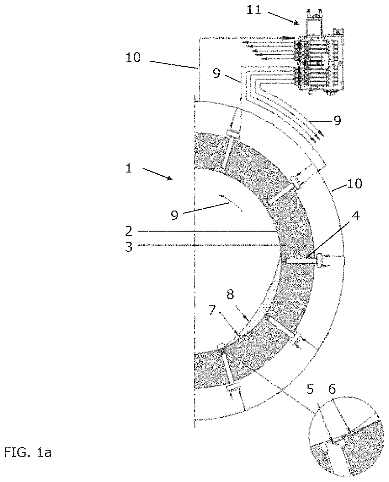
[0052]FIG. 1a illustrates one half of a cylinder of a large slow-running two-stroke engine, for example marine diesel engine. The cylinder 1 comprises a cylinder liner 2 on the inner side of the cylinder wall 3. Inside the cylinder wall 3, there are provided a plurality of lubricant injectors 4 distributed along a circle with identical angular distance between adjacent injectors 4. The injectors 4 receive lubrication oil from a lubricator pump and controller system 11 through lubrication supply lines 9. The supplied oil is typically heated to a specific temperature, for example 50-60 degrees. Some of the lubricant is returned to the pump by lubricant return lines 10. The lubricator pump and controller system 11 supplies pressurised lubrication oil to the injectors 4 in precisely timed pulses, synchronised with the piston motion in the cylinder 1 of the engine. For the synchronisation, the lubricator pump and controller system 11 comprises a computer that monitors parameters for the ...


PUM


Abstract

Disclosed is lubrication for a slow-running two-stroke engine, especially marine diesel engines. The lubrication uses Swirl Injection Principle by locating the lubricant injectors closer to the TDC than ⅕ of the full stroke of the piston, which is closer than in typical marine diesel engines. This can be achieved by reconstructing cylinder liners or by adding new mounting holes to the cylinder. In case that such reconstruction is not possible, an improvement of SIP principles can also be achieved by directing the spray towards the TDC or to a location on the cylinder liner closer to the TDC as compared to the location of the SIP valves, for example under an angle of more than 30 degrees or even more than 60 degrees when measured from a plane normal to the cylinder axis.

Description

CROSS-REFERENCE TO RELATED APPLICATIONS[0001]This application claims priority to PCT Application No. PCT / DK2015 / 050329 having a filing date of Oct. 28, 2015, the entire contents of which is hereby incorporated by reference.FIELD OF TECHNOLOGY[0002]The following relates to a large slow-running two-stroke engine, for example marine diesel engine or gas or diesel engine in a power plant, with lubricant injector near the Top Dead Center (TDC) of the piston in the cylinder.BACKGROUND[0003]Due to the focus of on environmental protection, efforts are ongoing with respect reduction of emissions from marine engines. This also involves the steady optimization of lubrication systems for such engines. Thereto is added increased competition and the economic aspects of reducing oil consumption, as this is a significant part of the operational costs of ships. A further concern is proper lubrication despite reduced lubricant because the longevity of diesel engines should not be compromised by the r...

Claims


Application Information

Patent Timeline
Patent Type & Authority Patents(United States)
IPC IPC(8): F01M1/08F01M11/02F01M1/20F02F1/20F16N7/38
CPCF16N7/38F01M1/08F01M11/02F02F1/20F01M2011/022F01M2001/083F02B75/02F02B2075/025
Inventor BENNEDSEN, NICK PAW
Owner HANS JENSEN LUBRICATORS
Why Eureka
Try Eureka