
Relative position detection means and displacement detection device

a technology of relative position and detection means, applied in the direction of instruments, polarising elements, optical elements, etc., can solve the problems of difficult to correspond to a wide signal period without changing parts, and achieve the effect of simple structure, stable and high-precision detection of displacement, and simple structur

Active Publication Date: 2020-08-18
DMG MORI CO LTD
View PDF5 Cites 0 Cited by
  • Summary
  • Abstract
  • Description
  • Claims
  • Application Information

AI Technical Summary

Benefits of technology

This configuration allows for stable and high-precision detection of displacement over a wide range of signal periods with a simple structure, ensuring accurate output of relative position information while maintaining precision.

Problems solved by technology

Therefore, it was difficult to correspond to wide signal period without changing parts provided in the displacement detection device.

Method used


Image

  • Relative position detection means and displacement detection device
  • Relative position detection means and displacement detection device
  • Relative position detection means and displacement detection device

Examples


Embodiment Construction

[0056]Hereinafter, it is explained in detail about preferred embodiments of the present invention. In addition, the embodiments of the present invention explained in the below should not unjustly limit the content of the present invention described in claims, and not all of the features explained in the embodiments of the present invention are necessary as means for solving the problem of the present invention. Also, figurations of various lenses described in the following explanation may be any kind of figuration as long as it is having prescribed imaging performance, and it may be a single lens or a group of lenses with spherical surface or aspherical surface, or it may be a diffraction grating having imaging function.

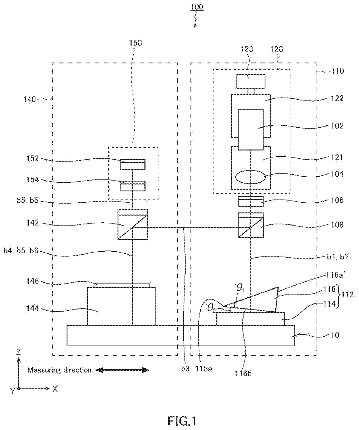
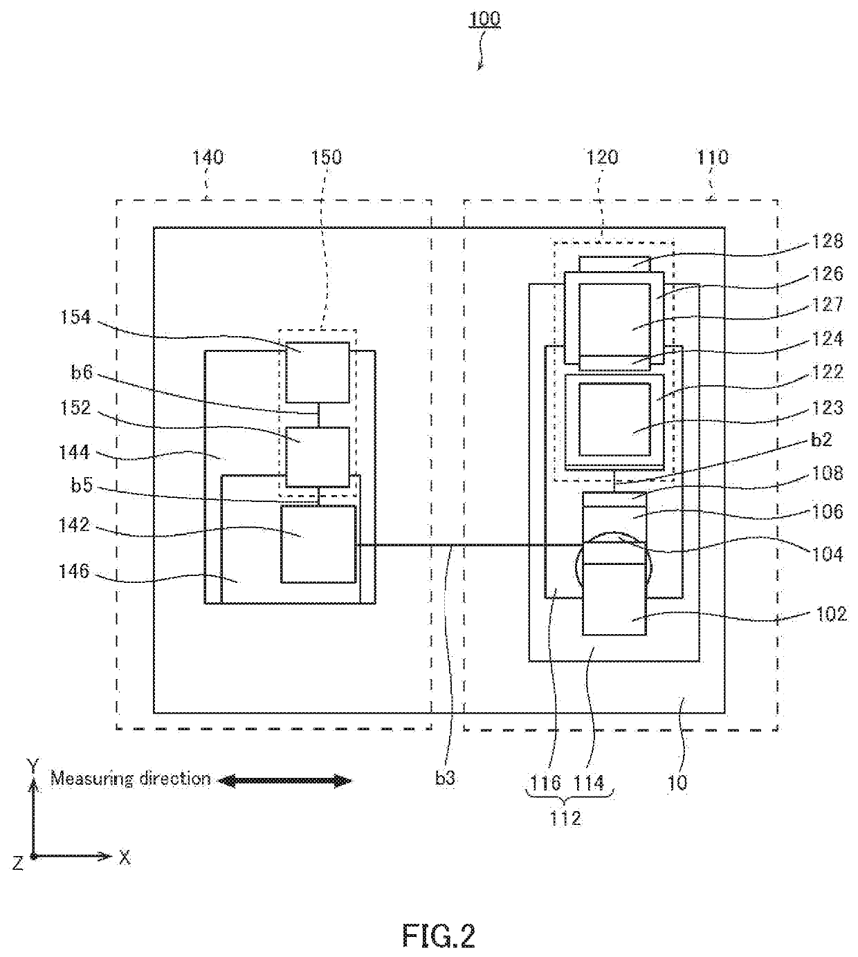
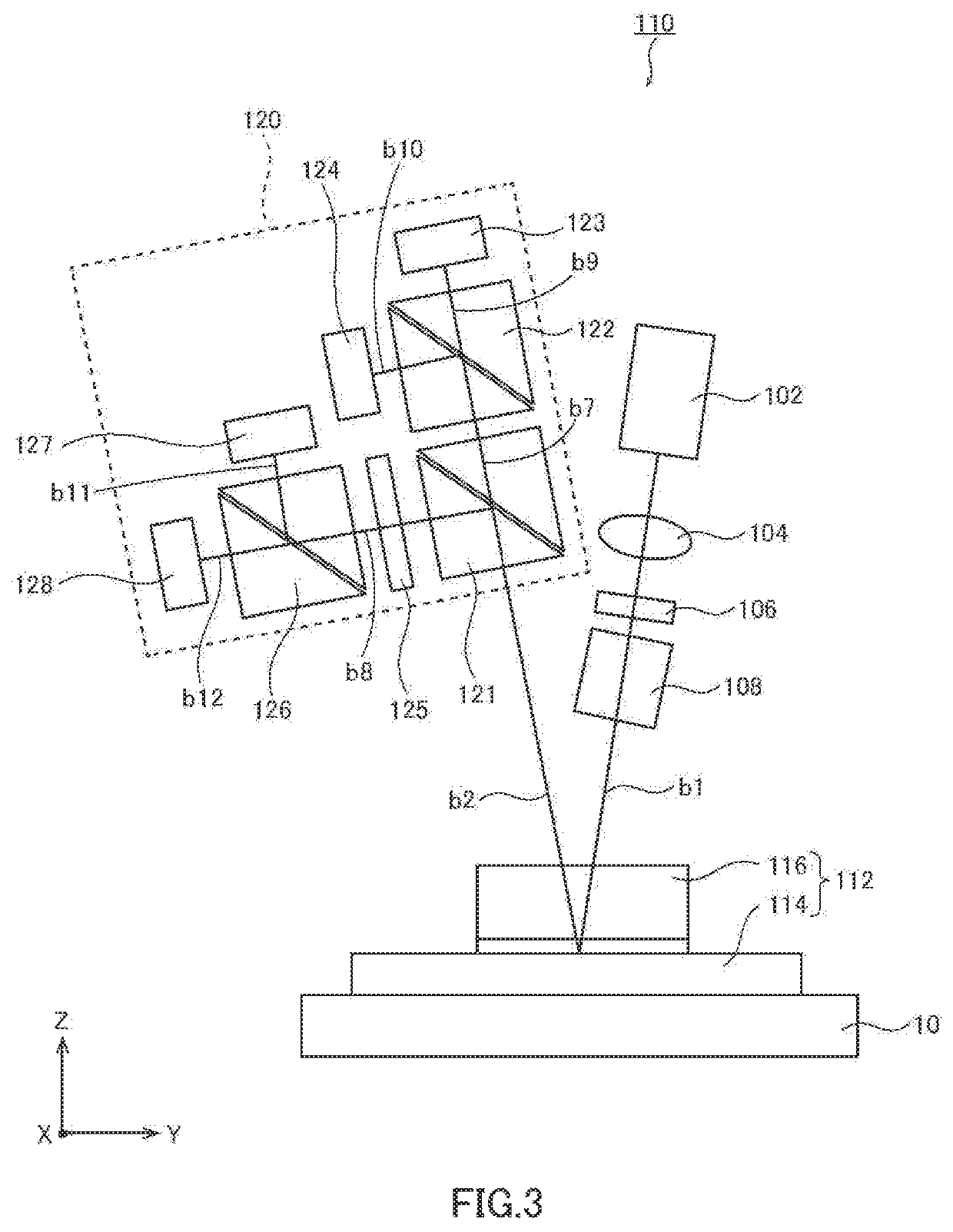
[0057]At first, explaining about the configuration of a displacement detecting device relating to one embodiment of the present invention, by using drawings. FIG. 1 is a front view illustrating an outline of a structure of a displacement detection device relating to ...


PUM

PropertyMeasurementUnit
wavelengthaaaaaaaaaa
angleaaaaaaaaaa

Abstract

Example position detection means and displacement detection devices are described. A relative position detection means optically detects a relative position of displacement of an object to be measured in a measuring direction, including a target mounted on the object to be measured and irradiated with light from a light source; a light receiver for detection of relative position for receiving light by changing polarization state of reflected light at the target with respect to the light; and a relative position information output unit for outputting relative position information based on displacement of the target in the measuring direction based on change of polarization state of the reflected light. The target includes a reflector mounted on the object to be measured and a birefringent member on the reflector and having a thickness changing from a tip to a base end along the measuring direction.

Description

BACKGROUND OF THE INVENTIONField of the Invention[0001]The present invention relates to a relative position detection means provided in a displacement detection device for detecting a displacement of a movable part of a machine tool, a semiconductor manufacturing device or the like, and also, to a displacement detection device provided with the relative position detection means. In addition, the present application claims priority based on Japanese Patent Application No. 2017-149766 filed in Japan on Aug. 2, 2017, Japanese Patent Application No. 2017-153710 filed in Japan on Aug. 8, 2017, Japanese Patent Application No. 2017-184103 filed in Japan on Sep. 25, 2017, Japanese Patent Application No. 2018-025747 filed in Japan on Feb. 16, 2018, which are incorporated by reference herein.Description of Related Art[0002]From the past, a displacement detection device using light has been utilized widely as a contactless measuring device of displacement of an object to be measured. The displ...

Claims


Application Information

Patent Timeline
Patent Type & Authority Patents(United States)
IPC IPC(8): G03F7/20G02B5/30G01B11/26G01D5/28G01D5/30G01B11/14G01D5/34G02B6/34G02B27/28
CPCG01D5/344G01D5/285G01B11/14G01D5/30G01B11/26G02B5/3083G02B27/283G02B6/34
Inventor OKUYAMA, SHUNSUZUKI, AKINORI
Owner DMG MORI CO LTD
Learn More