Gynaecological module and apparatus

a gynaecological module and gynecological technology, applied in the field of medical devices and methods, can solve the problems of not being able to allow all instruments to enter or exit, affecting the safety of women's health, and not being able to absorb the force of the gynecological module,

Active Publication Date: 2020-08-25
ASPIVIX SA
View PDF14 Cites 2 Cited by
  • Summary
  • Abstract
  • Description
  • Claims
  • Application Information

AI Technical Summary

Benefits of technology

[0026]The hollow rod is rigid to move / pull the suction module accurately and precisely.
[0031]The hollow rod is made with transparent material to enhance the visibility for the practitioner.

Problems solved by technology

To achieve its grasping effectiveness, tenaculum is obviously painful, traumatic, triggering often bleeding and sometimes iatrogenic lesions of the cervix.
Moreover, no matter how the sterilization process is, non-disposable instruments are associated with a risk of contamination in case of inappropriate sterilization.
While their non-traumatic aspect was unproven, the grasping effectiveness is seen as insufficient.
Despite of these clear drawbacks, due to lack of alternative, tenaculum is widely used in gynaecology and obstetrics to grip and pull the cervix.
However this solution uses a closed suction part with a form that renders the central tunnel too narrow, and does not allow all instruments to enter or exit preventing the correct execution of some gynaecological procedures.
A problem encountered comes from the natural anatomy of females; the cervix is at an angle relative to the vaginal canal.
Another problem encountered is the visibility through the vagina during the execution of the procedure.

Method used


Image

  • Gynaecological module and apparatus
  • Gynaecological module and apparatus
  • Gynaecological module and apparatus

Examples


first embodiment

[0058]FIGS. 1 to 7 now described are in relation to the invention.

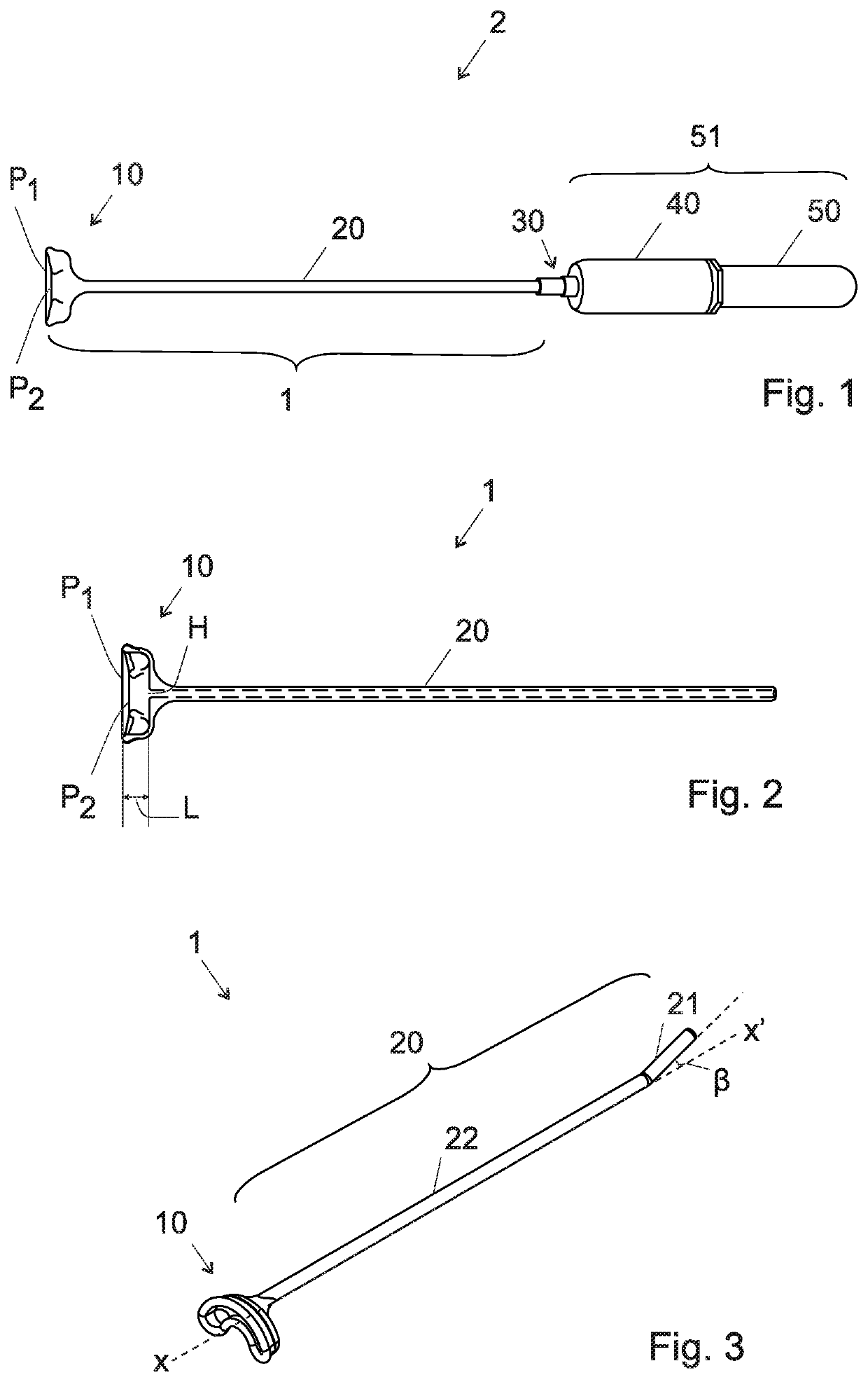
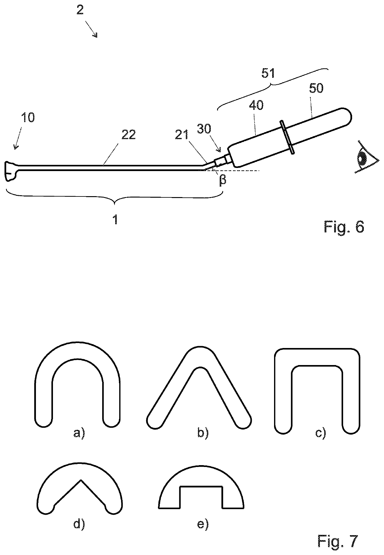
[0059]FIG. 1 gives a general view of the whole apparatus 2 comprising, from the proximal end to the distal end, a vacuum system 51 including a vacuum reserve source 50 and a support of the vacuum reserve source 40, a connector 30 and the suction module 1. As known per se, the vacuum reserve source 50 and the support of the vacuum reserve source 40 cooperate to form a pump that can be manually activated by a reciprocal sliding motion of the vacuum reserve source 50 within the support 40 of the vacuum reserve source which has open proximal end (on the right side in FIG. 1) which can accommodate a segment of the vacuum tube. Alternatively, an electrical motor can activate the reciprocal motion.

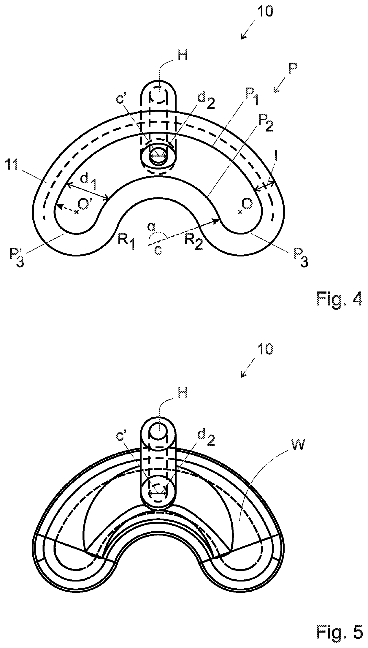
[0060]The suction module 1 comprises a suction chamber 10 and a hollow rod 20.

[0061]In a variant the hollow rod 20 can be straight as illustrated in FIGS. 1 and 2.

[0062]In another variant the hollow rod 20 can include a straight pa...

second embodiment

[0094]FIGS. 8 to 11 now described are in relation to the invention.

[0095]FIG. 8a gives a general view of the whole apparatus 2 comprising, from the distal end to the proximal end, the suction module 1 and a vacuum system comprising a vacuum reserve rod 60 defining a sealed enclosure and comprising an elongated portion with a distal end closed by a pierceable element 65.

[0096]FIG. 9 shows an exploded view of the vacuum reserve rod 60. The elongated portion comprises three aligned portions extending along the main direction of the apparatus 2. The elongated portion has preferably two cylindrical first and second portions 63, 64 having different diameters, and a loop portion 61 attached to the first cylindrical portion 63. The distal end of the second portion 64 is closed by a pierceable element 65 making the vacuum reserve rod 60 defining a sealed enclosure and allowing maintaining the vacuum in the vacuum reserve rod 60.

[0097]The vacuum reserve rod 60 comprises a shoulder 62 along th...


PUM


Abstract

A gynecological suction module (1) comprising a hollow rod (20) and a suction chamber (10) connected to the hollow rod by a hole (H) for fluid connection, the aforesaid suction chamber being configured to engage the surface of the vaginal portion of the cervix, the aforesaid suction chamber (10) being delimited by a concave wall W defined by an edge (P) having a C shape and comprising an external portion (P1), an internal portion (P2) and two end portions (P3, P3′), wherein said internal edge P2 is out of the plane defined by said external portion P1.

Description

FIELD OF THE INVENTION[0001]The present invention concerns medical devices and methods used during multiple gynaecological procedures. More specifically, the present disclosure relates to methods and apparatus used to grasp and / or manipulate the cervix.DESCRIPTION OF RELATED ART[0002]Grasping cervix is essential in many very common gynaecological procedures, some listed below: IUCD (intra uterine contraception device) insertion and removal, uterine tissue swab (endometrial) for diagnostic purpose, cervix dilatation for uterus cavity curettage, cervix dilatation for hysteroscopy (camera in uterus), measuring uterine cavity size during surgery, hysterosalpingography (imaging procedure of the uterine cavity and fallopian tubes for fertility check-up).[0003]To execute the procedures, the tenaculum also called Claw forceps or Pozzi with their dozen of variants have been used for over a century. This instrument which features stainless steel jaws ending in sharp inward-pointing hooks for ...

Claims


Application Information

Patent Timeline
Patent Type & Authority Patents(United States)
IPC IPC(8): A61B17/42A61B1/303A61F6/18A61B10/02A61B17/00A61B17/30
CPCA61B17/4241A61B1/303A61F6/18A61B17/42A61B2017/00561A61B2017/4225A61B10/0291A61B2217/005A61B2017/308A61B2017/00907A61B2017/306
Inventor FINCI, DAVIDFINCI, JULIENHORRAS, MATHIEU
Owner ASPIVIX SA
Why Eureka
Try Eureka