Tamper evident assembly

Active Publication Date: 2020-09-01
INT MEDICAL INDS
View PDF355 Cites 17 Cited by
  • Summary
  • Abstract
  • Description
  • Claims
  • Application Information

AI Technical Summary

Benefits of technology

[0011]The assembly of the present invention further includes a connector assembly adjustably and fixedly connecting the elongated tether to the cover, so as to assume an operative position. In at least one embodiment, the connector assembly is connected directly to or in direct association and/or adjacent relation to the cover so as to establish and maintain both the tether and the cover concurrently in a position which prevents or restricts removal of the stopper or piston on the plunger of the syringe from the open end of the syringe barrel. Further, the tamper evident assembly of the present invention includes cooperative structuring between the connector assembly and at least the distal end of the elongated tether, so as to establish a one-way drive or passage of the distal end through the connector assembly. Such a one-way passage or direction of travel facilitates a stable, fixed connection between the cover and the distal end of the tether and may be accomplished by a ratchet connector or other appropriate structure.
[0012]The operative position is further defined by the proximal end of the tether being connected to the barrel of the syringe, preferably at an opposite end thereof, so as to be disposed in a “removal preventing relation” with the plunger of the syringe, and preferably, the stopper or piston thereof. As such, the proximal end of the tether is at least partially disposed within a portion of the hollow interior of the syringe barrel s

Problems solved by technology

As a result, a pre-loaded syringe may travel quite some distance and be handled by several people before it reaches a nurse's station, which raises some concern that the contents of the syringe may be tampered with or cause the sterility of the syringe and/or its contents to be compromised.
Additionally, in the case where a drug has been prescribed that is a very expensive or addictive, such as but not limited to morphine, has been pre-loaded in the syringe or other administering device, there is a danger that the pre-loaded syringe or other administering device will be tampered with at some point, by a person seeking unauthorized access to the drug.
This possibility can present a real danger if such a pers

Method used


Image

  • Tamper evident assembly
  • Tamper evident assembly
  • Tamper evident assembly

Examples


Embodiment Construction

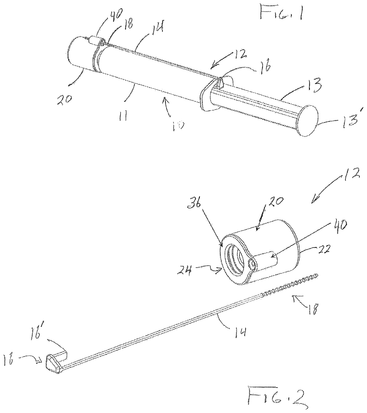
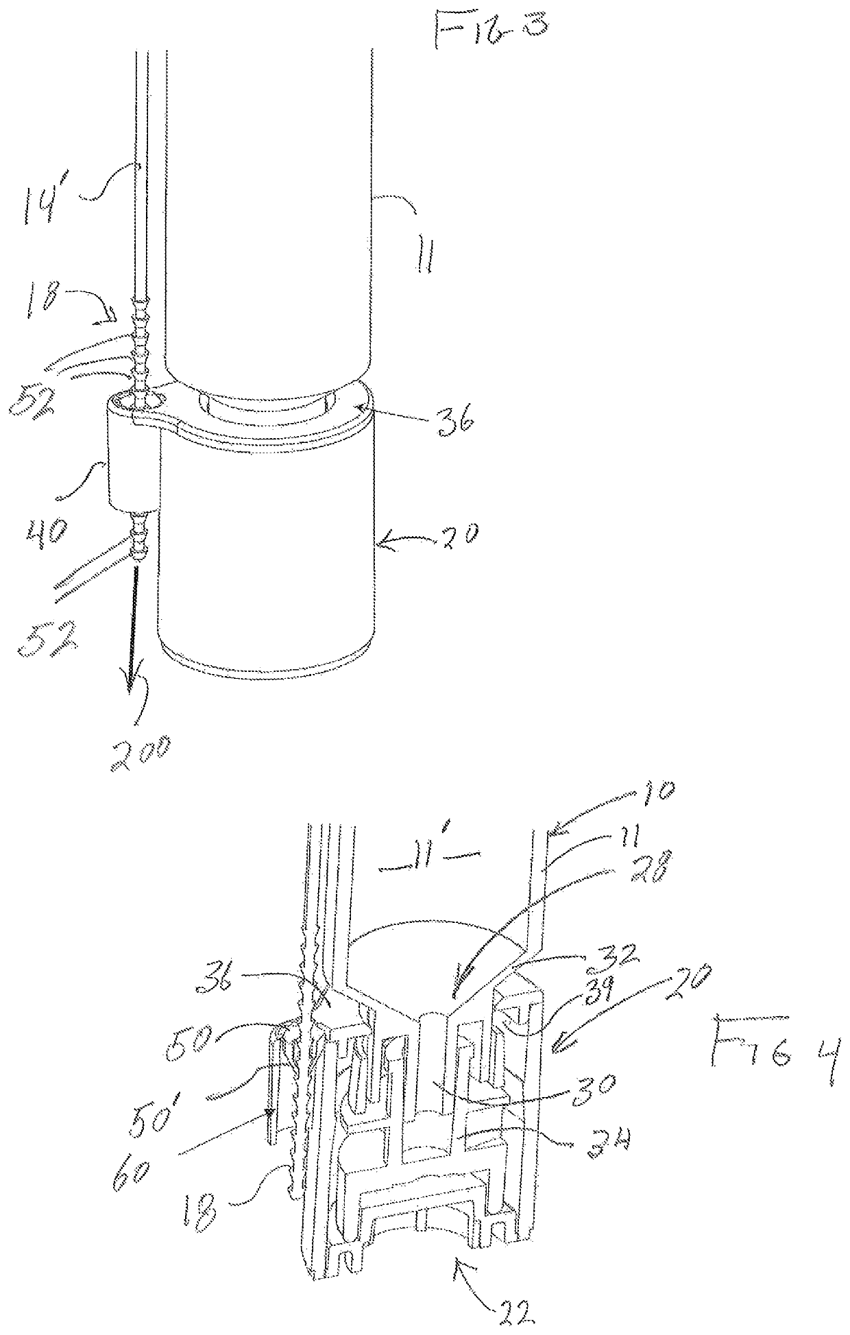
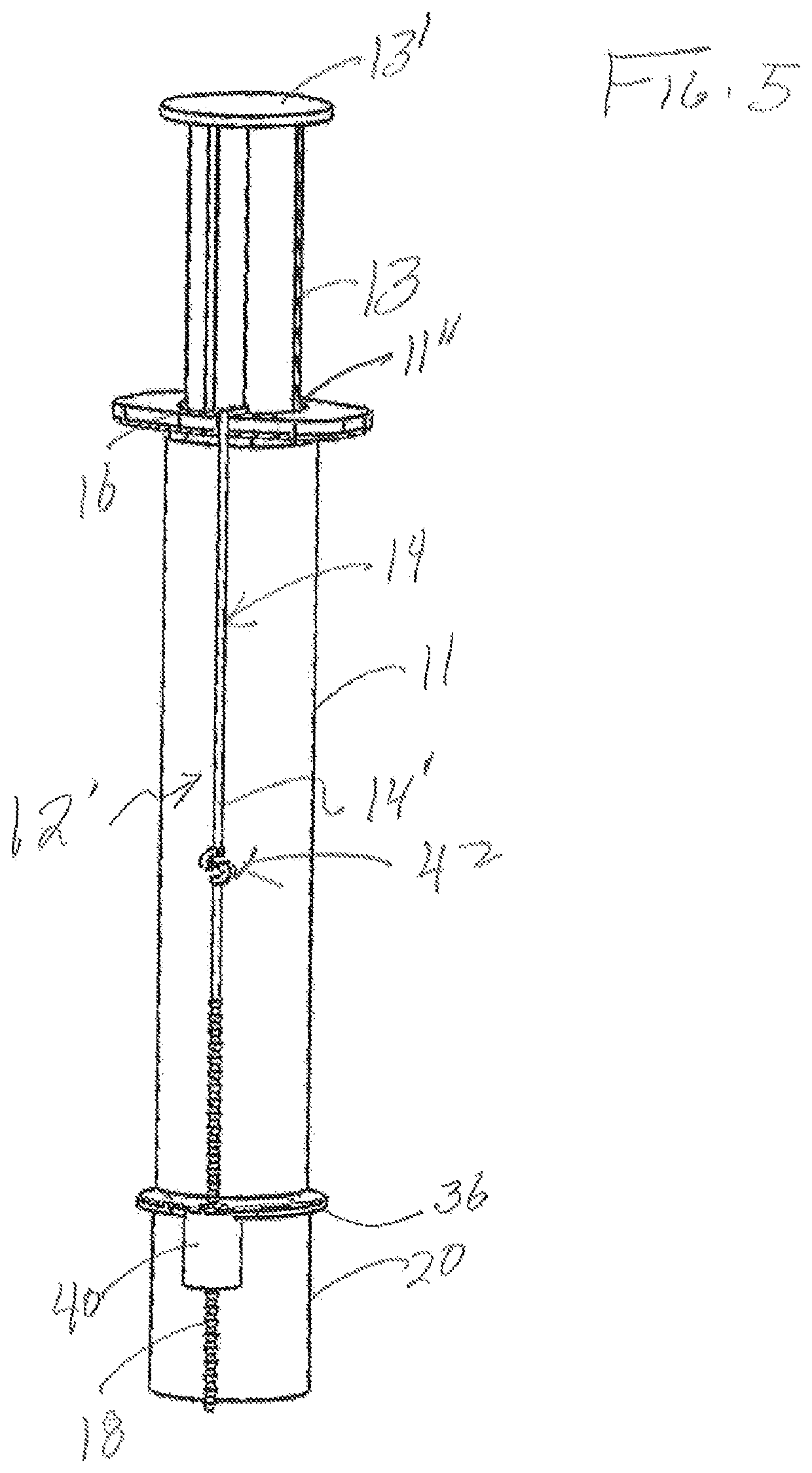
[0030]As represented throughout the Figures, the present invention is directed to an assembly, structured to have tamper evident capabilities, which prevents or restricts access to the interior of a syringe, generally indicated as 10 such as, but not limited to, a syringe that has been filled with a drug, medicine or other content. In the illustrated embodiment of FIG. 1, the tamper evident assembly 12 of the present invention is represented in a completed and assembled operative position. Further, when in this assembled and operative position, the tamper evident assembly 12 is disposed in cooperative connection, attachment or otherwise in direct association with the syringe 10 of the type including a barrel 11 and a hollow interior 11′ (shown in FIG. 4) in which a drug, medicine or other contents may be filled and stored for a period of time. Also, and as perhaps best shown in FIGS. 7 and 7A, the syringe 10 includes an open end 11″ through which a plunger 13 enters the hollow inter...


PUM


Abstract

A tamper evident assembly for retaining a plunger and piston within a barrel of a syringe including an elongated tether and a cover connected to the tether and concurrently disposed in an operative position on the syringe. A connector assembly adjustably and fixedly interconnects the tether to the cover in the operative position, wherein the cover is connected in covering relation to a discharge port of the syringe concurrently to a proximal end of the tether being connected to the syringe barrel in a removal preventative relation to the piston. Movable adjustment of the tether relative to the connector assembly defines a retaining segment disposed into a taut, fixed length orientation between the proximal end of the tether and the cover, to further define the operative position.

Description

CLAIM OF PRIORITY[0001]The present application is based on and a claim of priority is made under 35 U.S.C. Section 119(e) to a provisional patent application in the U.S. Patent and Trademark Office, namely, that having Ser. No. 62 / 466,701 and a filing date of Mar. 3, 2017, which is incorporated herein by reference in its entirety.BACKGROUND OF THE INVENTIONField of the Invention[0002]This invention is directed to a tamper evident assembly structured to restrict access to a drug or other contents in a loaded syringe by preventing removal of the syringe plunger and / or piston from the interior of the syringe barrel, through the open end thereof. Disconnection of the tamper evident assembly from an intended “removal preventing relation” to the piston is at least one indication of tampering with or use of the syringe.Description of the Related Art[0003]In the medical field, it is a relatively common for authorized medical personnel to prescribe a drug or medication for a patient which is...

Claims


Application Information

Patent Timeline
IPC IPC(8): A61M5/50A61M5/31
CPCA61M5/3135A61M5/3134A61M5/5086A61M2205/276
Inventor VITELLO, JONATHAN J.HUNT, TIMOTHY BRANDONBANIK, ROBERT
Owner INT MEDICAL INDS
Why Eureka
Try Eureka