Electronic dosing drive

Active Publication Date: 2020-09-01
EPPENDORF AG
View PDF33 Cites 2 Cited by
  • Summary
  • Abstract
  • Description
  • Claims
  • Application Information

AI Technical Summary

Benefits of technology

The patent describes the benefits of producing threaded spindles using injection molding and MIM methods. The patent also discusses the use of clearance fits between guide areas and internal threads to minimize friction. The clearance fit is important to prevent interference between parts and ensure smooth operation. The patent also mentions the use of guide ribs for achieving low-friction guiding in the spindle nut and the placement of the parting plane of the injection molding tool. The guide ribs can also have a second flattening with guide areas to prevent demolding burrs during production. Overall, the patent focuses on improving the production and performance of threaded spindles through these methods.

Problems solved by technology

A disadvantage is the complex manufacturing of the threaded spindle by means of highly precise lathes and finishing, for example by deburring.
Furthermore, a hitting of the threaded spindle can occur if it protrudes farther out of the spindle nut with the non-guided end.
The spindle drive is susceptible to corrosion.
Corrosion increases the friction and therefore the wear as well as decreasing the dosing accuracy.
Overload can lead to plastic deformation which also lowers the precision of the spindle drive.

Method used


Image

  • Electronic dosing drive
  • Electronic dosing drive
  • Electronic dosing drive

Examples


Embodiment Construction

[0077]In the present application, “up” and “down” as well as indicators derived therefrom refer to a vertical orientation of the threaded spindle and arrangement of the drive motor above the threaded spindle.

[0078]Features of various exemplary embodiments that are addressed with the same terms are provided with the same reference signs in the following.

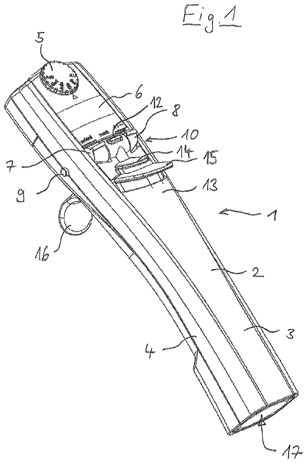
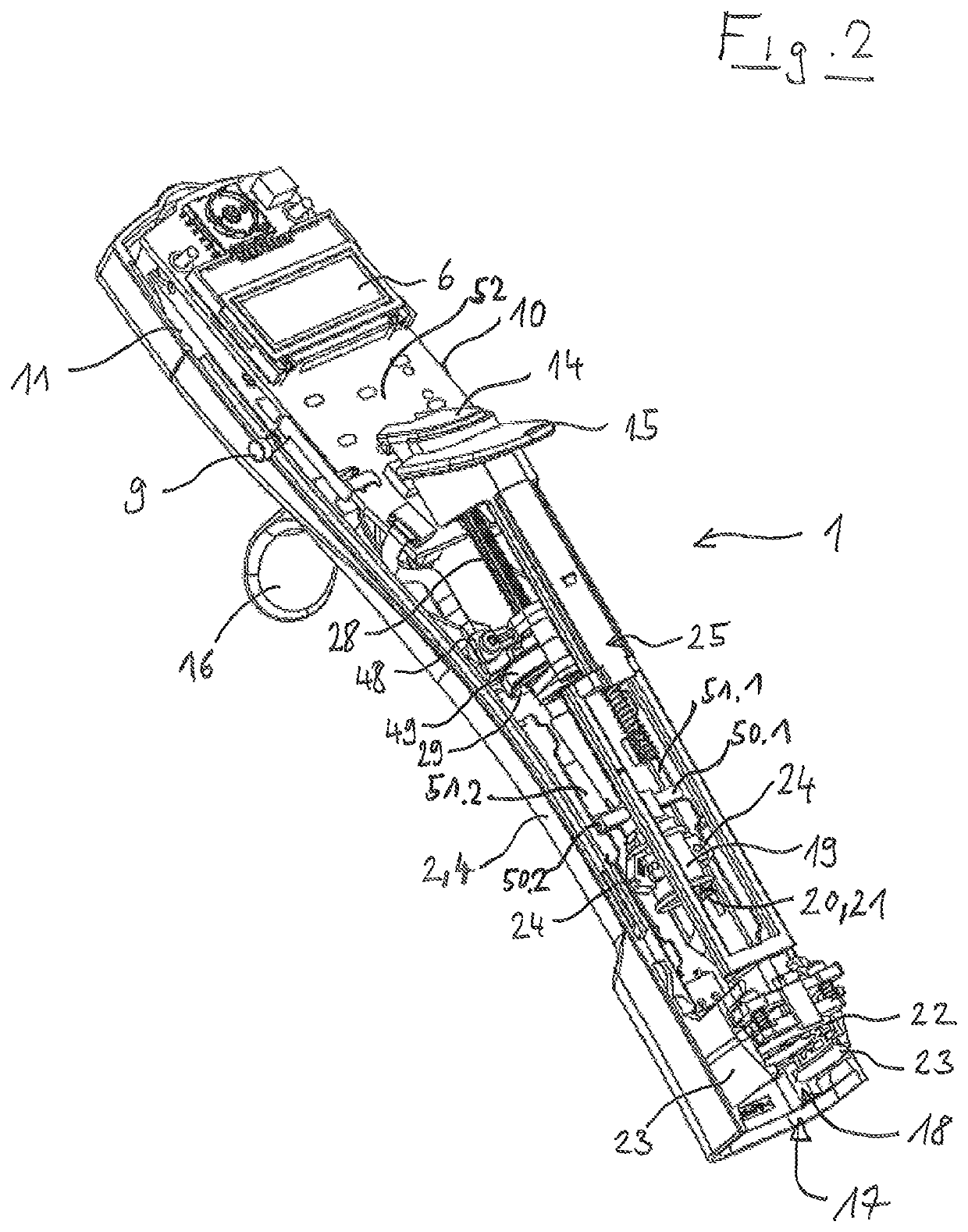
[0079]The electronic manual dosing device 1 according to FIGS. 1 and 2 is an electronic manual dispenser. It has a rod-shaped housing 2 that is divided in the longitudinal direction into a front housing hull 3 and a rear housing hull 4.

[0080]On the front side of the housing 2, a selection wheel 5 for selecting the respective operating mode is located on the upper end. By means of the selection wheel 5, the dosing functions pipetting, dispensing and titrating, for example, can be set.

[0081]Under that, a display 6 is recessed into the front side of the housing 2.

[0082]Beneath the display 6, two rocker switches 7, 8 that serve to call up...


PUM


Abstract

An electronic dosing drive comprising a support structure, a threaded spindle with an external thread for driving a plunger, at least one first guide element is firmly connected, and is guided parallel to the threaded spindle on a second guide element, a spindle nut having an internal thread is engaged with the external thread of the threaded spindle, an electric drive motor having a motor shaft is coupled with the spindle nut and is attached to the support structure, an electric control apparatus is connected to the electric drive motor, where the external thread of the threaded spindle has multiple threaded areas that are separated from each other by first flattenings on their circumference extending in the longitudinal direction, and the first flattenings have guide areas that abut the core diameter of the internal thread of the spindle nut.

Description

Cross-Reference to Related Applications[0001]This application claims priority to European Patent Application Number 17 169 764.2 filed May 5, 2017, the entire contents of which being incorporated by reference herein.[0002]The invention relates to an electronic dosing drive comprising a spindle drive and an electronic drive motor for driving a plunger in a cylinder.BACKGROUND OF THE INVENTION[0003]Electronic dosing devices are utilized in particular in scientific and industrial laboratories with medical, molecular biological and pharmaceutical areas of application for dosing liquids. Electronic dosing devices have an electronic dosing drive for driving a plunger in a cylinder. In direct displacement systems, the dosing device is coupled with an exchangeable syringe. The electronic dosing drive drives a syringe plunger in a syringe cylinder of the syringe, through which the receiving of liquid into the syringe and the discharge of liquid from the syringe is controlled. In doing this, ...

Claims


Application Information

Patent Timeline
IPC IPC(8): B01L3/02F16H25/24
CPCF16H25/24B01L3/0227B01L3/0289F16H2025/249F16H2025/2481
Inventor REICHMUTH, BURKHARDTWILTH, MARCSATTLER, JÖRG
Owner EPPENDORF AG
Why Eureka
Try Eureka