Compressor element for a screw compressor and screw compressor in which such a compressor element is applied

a compressor element and compressor technology, applied in the direction of machines/engines, rotary/oscillating piston pump components, liquid fuel engines, etc., can solve the problems of increased bearing load, increased costs, and affecting the cost of compressor elements, so as to avoid the installation of pipes and reduce the risk of leakage

Active Publication Date: 2020-09-01
ATLAS COPCO AIRPOWER NV
View PDF27 Cites 0 Cited by
  • Summary
  • Abstract
  • Description
  • Claims
  • Application Information

AI Technical Summary

Benefits of technology

[0063]This also makes it possible for an input of the cooling jacket of the housing of the compressor element to be directly connected, in other words without the intervention of external pipes, to an output of the internal cooling channels of the housing of the gearwheel transmission.
[0064]As a result, the mounting

Problems solved by technology

A disadvantage of such force means is that it detrimentally affects the costs of the compressor element and that in some circumstances it also increases the load on the bearings instead of offsetting them such that larger bearings are required.
If plungers are used as a force means, the exerted force can be controlled, but such a control entails extra costs, makes the compressor element more vulnerable to possible breakdowns and increases the size and mass of the bearing cover and therefore also the forces and vibrations on the housing of the compressor element.
This has the disadvantage that in certain extreme conditions the axial bearing of the male rotor that is mounted on this axle journal can tilt, which can lead to a limitation of the operating region of the compressor element.
The known compressor elements of the discussed type are outlet driven, which means that the gearwheel transmission with the drive gearwheel is on the hot outlet side of the compressor element, whereby the axi

Method used


Image

  • Compressor element for a screw compressor and screw compressor in which such a compressor element is applied
  • Compressor element for a screw compressor and screw compressor in which such a compressor element is applied

Examples


Embodiment Construction

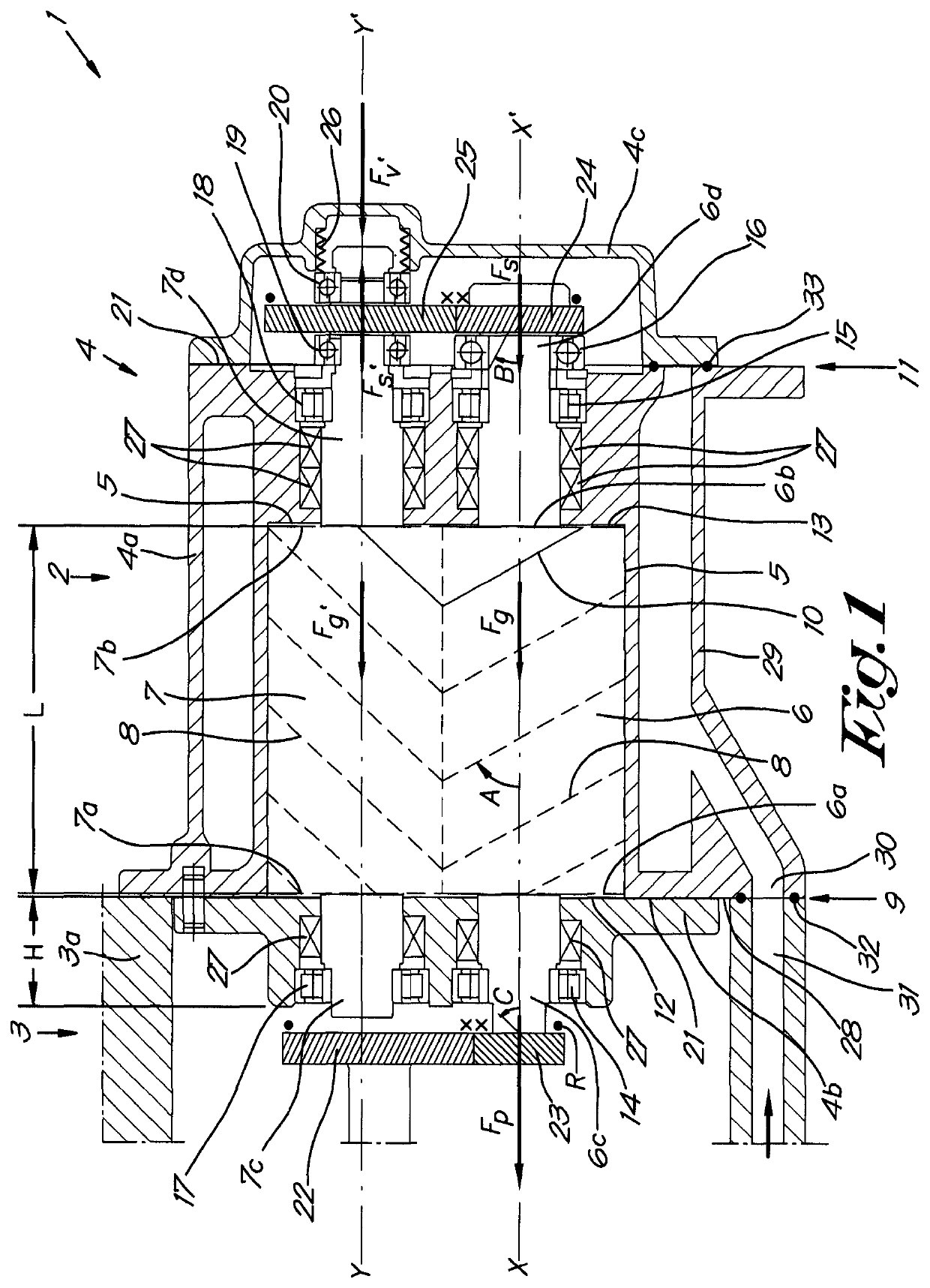
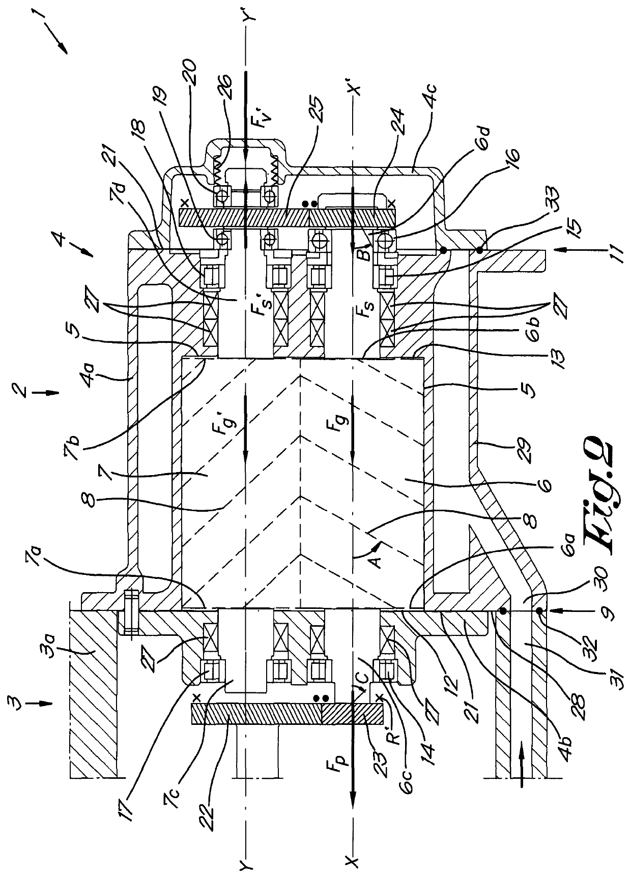
[0072]The screw compressor 1 shown in FIG. 1 comprises a compressor element 2 and a drive in the form of a gearwheel transmission 3, of which only a part is shown for reasons of clarity.

[0073]The compressor element 2 is provided with a housing 4 with a central section 4a in which two overlapping cylindrical rotor chambers 5 are provided, in which two rotors 6 and 7 are affixed with helical lobes 8, respectively a male rotor 6 and a female rotor 7 whose lobes 8 mesh together in such a way that chambers are separated between the rotors 6 and 7 which, when the compressor element 2 is driven, move in a known way from an inlet, not shown in the drawings, on the inlet side 9 of the rotors 6 and 7 to an outlet 10 on the outlet side 11 of the rotors 6 and 7, whereby during this movement the enclosed gas is compressed.

[0074]The axis lines X-X′ and Y-Y′ of the two rotors 6 and 7 are arranged practically parallel to one another and are held in an axial direction by their respective end faces 6...


PUM


Abstract

A compressor element of a screw compressor inlet side and an outlet side and two helical rotors, respectively a male rotor with a drive for the male rotor and a female rotor that is driven by the male rotor by means of synchronisation gearwheels with at least one synchronisation gearwheel on the male rotor, wherein the drive and synchronisation gearwheels of the male rotor are chosen such that, upon being driven with acceleration of the rotors without gas forces, the resulting mechanical drive force that is exerted by this drive and by this synchronisation gearwheel on the male rotor has an axial component that is directed from the outlet side to the inlet side and that the movement of the male rotor in the axial direction from the outlet side to the inlet side is fixed by means of a single axial single-acting or double-acting bearing.

Description

[0001]The present invention relates to a compressor element of a screw compressor for compressing a gas.BACKGROUND OF THE INVENTION[0002]Known compressor elements for the said type comprise a housing with an inlet for the gas on the inlet side and an outlet for the gas on the outlet side and two rotor chambers in which two helical rotors are mounted on bearings that mesh together when driven to compress the gas, respectively a male rotor with a drive gearwheel for driving the male rotor by a gearwheel transmission and a female rotor that is driven by the male rotor by means of synchronisation gearwheels with at least one synchronisation gearwheel on the male rotor and one synchronisation gearwheel on the female rotor, whereby the synchronisation gearwheels are generally designed such that, when driven, the male rotor rotates faster than the female rotor.[0003]By driving the compressor element, chambers are formed between the two rotors that are filled with gas at the inlet, whereby ...

Claims


Application Information

Patent Timeline
IPC IPC(8): F01C1/16F04C18/08F04C18/16F04C29/00F04C18/00F03C4/00F03C2/00
CPCF04C29/0071F04C18/086F04C29/0021F04C18/16F04C29/005F04C2240/50F04C2240/30
Inventor DE BOCK, SIMON PETER G.NACHTERGAELE, JOHANBERTELS, DIETER MANILLE L.
Owner ATLAS COPCO AIRPOWER NV
Why Eureka
Try Eureka