Piston pump comprising a piston with a profiled front face

a front face and piston technology, applied in the field of piston pumps, can solve problems such as the effect of affecting the efficiency of the piston pump by volum

Active Publication Date: 2020-09-22
ROBERT BOSCH GMBH
View PDF29 Cites 0 Cited by
  • Summary
  • Abstract
  • Description
  • Claims
  • Application Information

AI Technical Summary

Benefits of technology

[0004]The piston pump according to the invention is designed to reduce the dead space volume and thus to increase the efficiency of the piston pump.
[0005]For this purpose, it is envisaged according to the invention that the piston has, on its side facing a channel, a region which can be made to enter into the channel. In particular, this region is made to enter into the channel at least temporarily during a pump cycle. Typically, the channel is arranged fluidically between the compression chamber and the outlet valve, especially if the outlet valve and the inlet valve of the piston pump are arranged coaxially with one another. In particular, the channel is arranged directly upstream of the outlet valve and typically has a smaller diameter than a compression region at a distance from the outlet valve. By virtue of the region, the piston has a section which is designed to enter the channel, particularly during the compression phase or displacement phase of the pump cycle, and to compress or displace the fluid present there. As a result, the dead volume of the piston pump is reduced and the efficiency of the piston pump is increased.
[0006]In an advantageous development, it is envisaged that the outlet valve, the channel and the piston with the region are arranged along a common axis. The axis preferably lies in the direction of movement of the piston. This ensures that the piston pump has a particularly high efficiency since, during the compression phase, when the fluid leaves the compression chamber through the outlet valve, the fluid can flow in the same direction in which the piston is moving to leave the compression chamber.

Problems solved by technology

In many embodiments of the piston pump, especially in piston pumps with simultaneous inflow and outflow, there is the problem that there is a volume region in the compression chamber itself or directly adjoining the compression chamber in which the fluid present therein cannot be compressed or displaced or cannot be adequately compressed or displaced by the piston movement.
The size of the dead volume affects the efficiency of the piston pump.

Method used


Image

  • Piston pump comprising a piston with a profiled front face
  • Piston pump comprising a piston with a profiled front face

Examples


Embodiment Construction

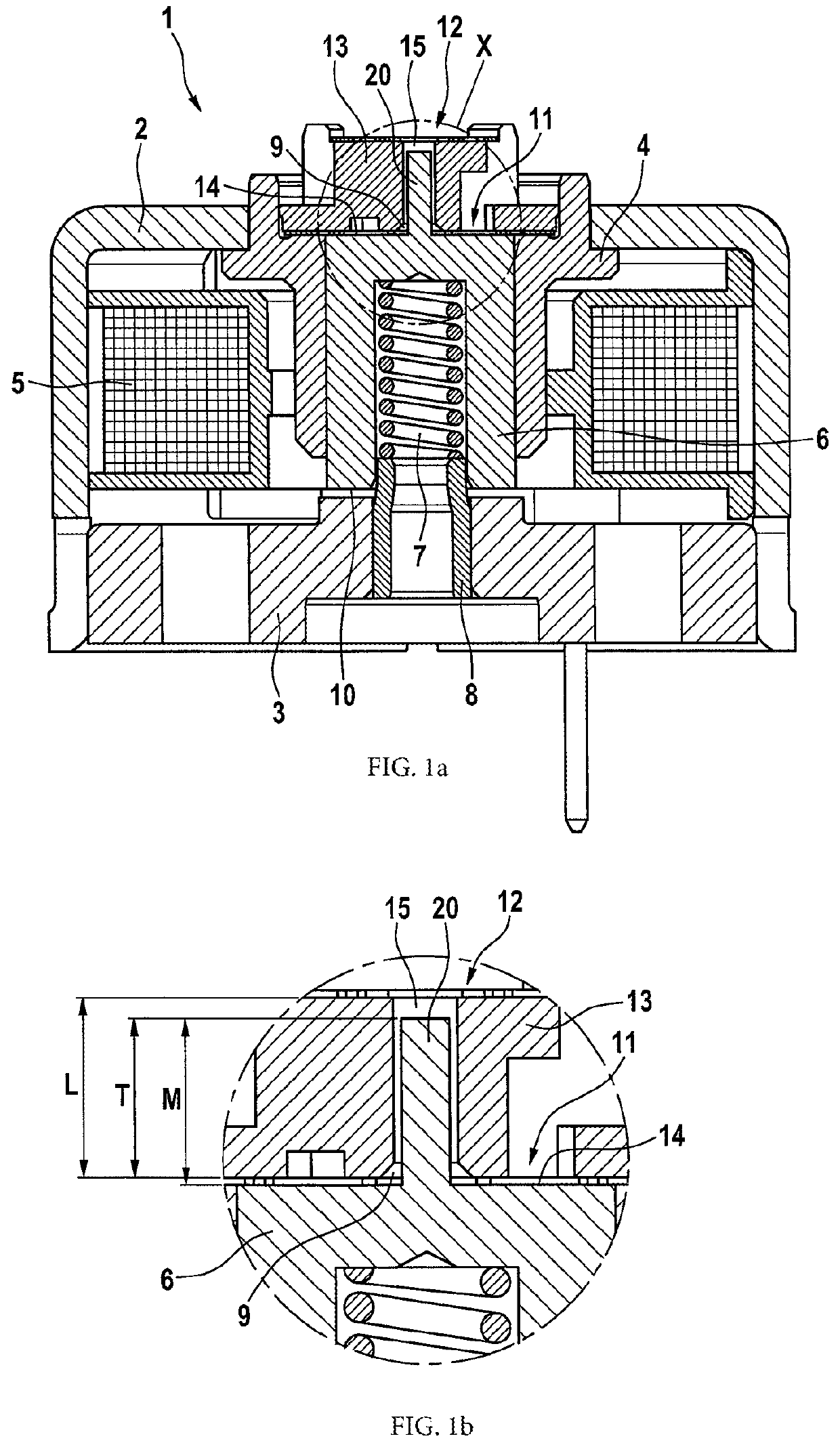
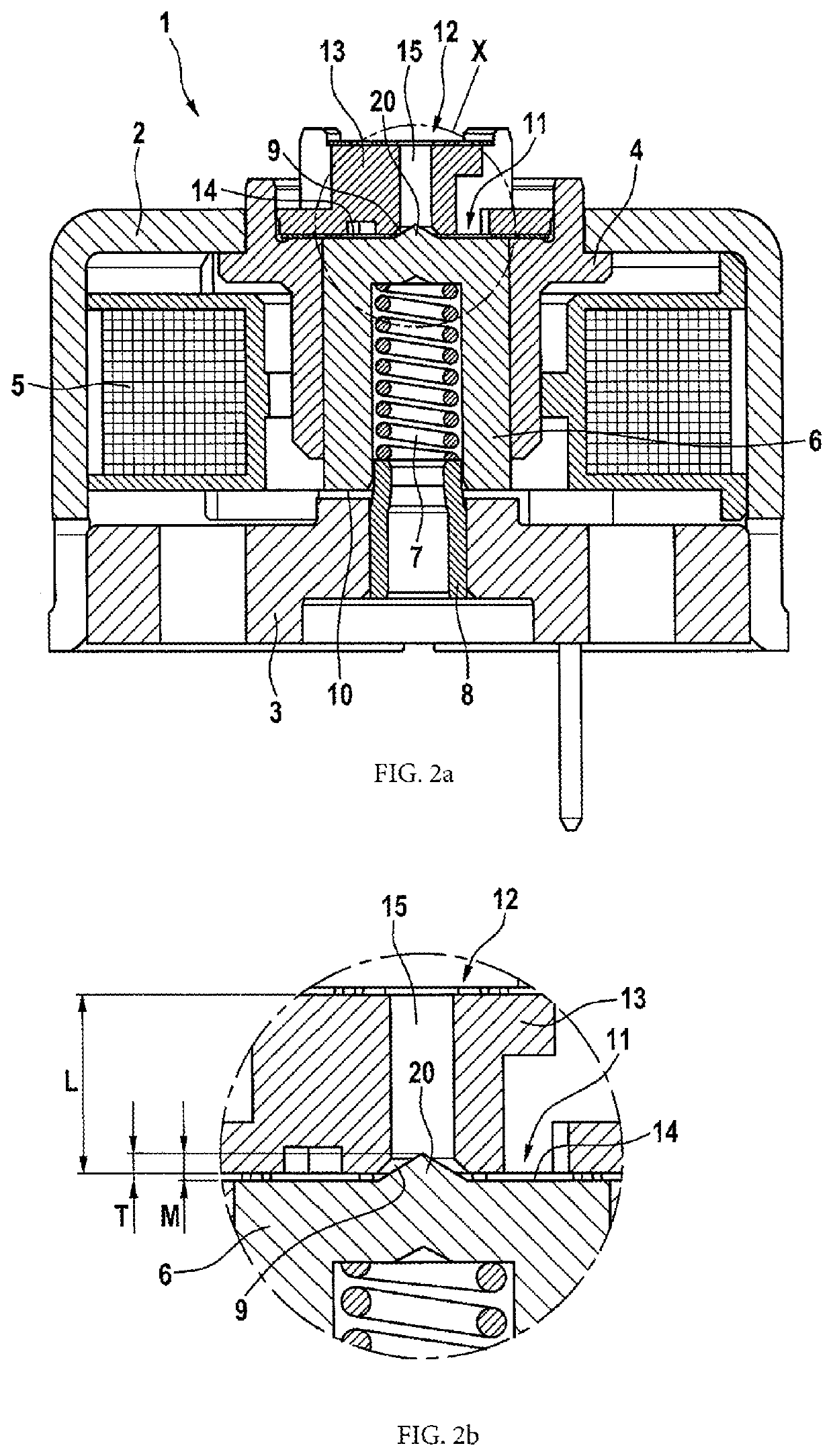
[0018]Two illustrative embodiments of the piston pump 1 according to the invention are shown in FIG. 1 and FIG. 2. The two illustrative embodiments differ in the precise configuration of the region 20 arranged on the end face 12 of the piston 6 which faces the channel 15. Part a) of each of the two figures shows a schematic illustration of a piston pump 1, wherein the basic construction of the piston pump 1 is the same in both illustrative embodiments. Part b) of each of the two figures shows an enlargement of the region X marked by a circle in part a) of the figures.

[0019]The basic construction of the piston pump 1 is described below. The piston pump 1 has a housing 2, an armature plate 3 and, for example, a solenoid 5 or solenoid set arranged in the housing 2. A cylinder 4 is arranged in the solenoid 5. A movable piston 6 is, in turn, arranged in the cylinder 4. The magnetic field produced by the solenoid 5 moves the piston 6 in the direction of the armature plate 3. On its side f...


PUM


Abstract

The invention relates to a piston pump, in particular for injection systems for motorized two-wheeled vehicles and / or for motorized three-wheeled vehicles, having a compression chamber, a piston, an inlet valve, and an outlet valve. A fluid can flow into the compression chamber via the inlet valve, and the fluid can flow out of the compression chamber via the outlet valve. A region in the form of a channel, which is arranged fluidically upstream of the outlet valve, in particular directly upstream of the outlet valve, has a cross-section which is reduced compared to a compression chamber region at a distance from the outlet valve. The invention is characterized in that a piston end face facing the channel has a region which can be immersed into the channel.

Description

BACKGROUND OF THE INVENTION[0001]The invention starts from a piston pump.[0002]Currently known piston pumps operate on the following principle: the piston, which is arranged and can be moved in a cylinder, is moved in the direction of an armature plate arranged on the rear side of the cylinder, e.g. by means of a magnetic field produced by a solenoid. During this process, a fluid, e.g. a fuel, is drawn via an inlet valve into a compression chamber, which is arranged between the inlet valve in the cylinder bottom and the piston. If the magnetic field is switched off, a spring, for example, which is arranged between the piston and the armature plate, pushes the piston back in the direction of the initial position and, in the process, compresses the fluid and pushes it out of the compression chamber via an outlet valve.[0003]In many embodiments of the piston pump, especially in piston pumps with simultaneous inflow and outflow, there is the problem that there is a volume region in the ...

Claims


Application Information

Patent Timeline
Patent Type & Authority Patents(United States)
IPC IPC(8): F04B53/02F04B17/04F04B53/00
CPCF04B53/02F04B17/044F04B53/008
Inventor PLISCH, ANDREASGIESLER, JURIJFLO, SIAMENDALLGEIER, THORSTENMAEURER, WALTERBAESSLER, LENA MAREN
Owner ROBERT BOSCH GMBH
Why Eureka
Try Eureka