Mechanical vapor recompression apparatus

a mechanical vapor and dryer technology, applied in lighting and heating apparatus, drying, energy-saving heating/cooling, etc., can solve the problems of insufficient scraping to prevent material build-up on the heating surface, difficult control of drying, continuous use, etc., to achieve fast cooking and drying process, simple and robust design, and large area

Active Publication Date: 2020-09-22
HEDINN
View PDF19 Cites 1 Cited by
  • Summary
  • Abstract
  • Description
  • Claims
  • Application Information

AI Technical Summary

Benefits of technology

[0009]The present invention provides a device and a method to overcome or ameliorate the aforementioned drawbacks of the prior art and to provide an improved and / or alternative and / or additional method or device for heating or removing a water phase from any material. The present invention provides a device with a simple and robust design with a large area for heat exchange and instead of moving the material in circles during rotation of the axis, the material is stirred with scrapers that scrape both the discs and the inner surface of the container. The present invention provides a faster process of cooking and drying and it prevents the material from burning on the surfaces of the device during the process. The heat exchange surface is therefore more efficient and the device easier to control. The present invention provides a device and a method where due to the fact that the discs do not connect to the whole circumference of the cylindrical portion of the container, in addition to the space above the discs, the organic material can travel easily from one space to another from the in-feed end to the out-feed end of the container. The present invention provides a device and a method where mechanical vapour recompression (MVR) technology is used to increase the temperature of the steam generated in the device and to use that steam to heat up at least a part of the heat exchange surfaces of the device. In a system and apparatus such as the one of the present invention, where steam from a boiler as well as secondary steam from the material being dried is used as heat exchange media, the secondary steam will always contain a large amount og light and heavy gases which will make the heat exchange process less efficient. By using individual discs which open into jackets surrounding the chamber, it is possible to use a set of discs for different jackets and thereby have different temperature and function in the part of the chamber with the different sets of discs and jackets. Furthermore, as the discs are connected to the jackets, it is possible to vent out the gases from the jackets during the process.
[0010]The present invention provides a new design which also provides a new type of dryer apparatus, where the function of dryer can be divided into two or more areas of the dryer chamber. One area can be defined by a separate jacket arranged around a part of the chamber of the dryer and conducting heating media from an outside source into the respective discs for that function area in the chamber. A second area can be defined by a separate jacket arranged around a part of the chamber using the MVR technology to take steam from the chamber and introducing the steam into the jacket for this function area. A third chamber can be defined by a separate jacket arranged around a part of the chamber and conducting steam from the chamber directly into the jacket arranged around this third function area of the dryer and thereby into the respective discs of that function area. The increased thermal conductivity, compared with conventional steam dryers, requires smaller heating surfaces to evaporate / dry a certain amount of moisture with relatively low temperature difference between sides.
[0011]It is the combination of a) the large area for heat exchange, b) the use of two or more sets of discs and jackets to divide the chamber into separate functional areas, and c) the use of the MVR technology to increase the temperature of the steam generated in the device and to use that steam to heat up at least a part of the heat exchange surfaces of the device, which provides the improved device resulting in an improved energy economical device and method for drying material. Furthermore, the device and the process provided by the present invention used for drying wet material only needs regulation by adjusting the amount of steam from a steam boiler into the first jacket to maintain a relatively constant low pressure inside the chamber. The new device also makes better use of the entire surface of the discs in the dryer. By using the MVR technology and effective large heat exchange surfaces obtained by individual discs connected to separate jackets, the apparatus of the present invention reduces considerably the energy usage in evaporation or drying of sticky liquid or of wet material.
[0025]In an embodiment of the present invention, the container is raised at the in-feed end above the out-feed end of the container. This is to facilitate the material to slowly migrate from the in-feed end towards the out-feed end of the container.
[0030]In an embodiment of the present invention, an MVR device, connected in a duct between the upper steam portion of the device and a jacket, receives steam at 100° C. and increases the pressure in the duct resulting in a temperature increase in the steam to 105-115° C. when introduced into the discs through the jacket.

Problems solved by technology

Material sticking to heat exchange surfaces makes control of drying problematic.
These devices need to be cleaned very frequently, which is time consuming and prevents continuous use.
The problems with such device are insufficient scraping to prevent material build-up on the heating surface and material can burn thereon.
Furthermore, it tends to be structurally heavy and expensive with a high resistance to rotation necessary for this application.
It is however limited in that it is difficult and expensive to increase the pressure / temperature mechanically of more than a few degrees, which means that relatively big heating surfaces are needed for each kg evaporated.
The problem with such a device is that new steam needs to be feed into the system as well to initiate the process.
Furthermore, the middle part of the axis and the discs will eventually contain gases which reduces the heat exchange capacity of the system.
It is possible to introduce steam of higher temperature, but that my result in the material burning against the disc surface during the heat exchange.

Method used


Image

  • Mechanical vapor recompression apparatus
  • Mechanical vapor recompression apparatus
  • Mechanical vapor recompression apparatus

Examples


Embodiment Construction

[0045]In the following, exemplary embodiments of the invention will be described, referring to the figures. The embodiments shown in the drawings are explained with reference numbers. These examples are provided to provide further understanding of the invention, without limiting its scope. The skilled person will understand that the drawings, described below, are for illustration purposes only. The drawings are not intended to limit the scope of the present teachings in any way.

[0046]In the following description, a series of steps are described. The skilled person will appreciate that unless required by the context, the order of steps is not critical for the resulting configuration and its effect. Further, it will be apparent to the skilled person that irrespective of the order of steps, the presence or absence of time delay between steps, can be present between some or all of the described steps.

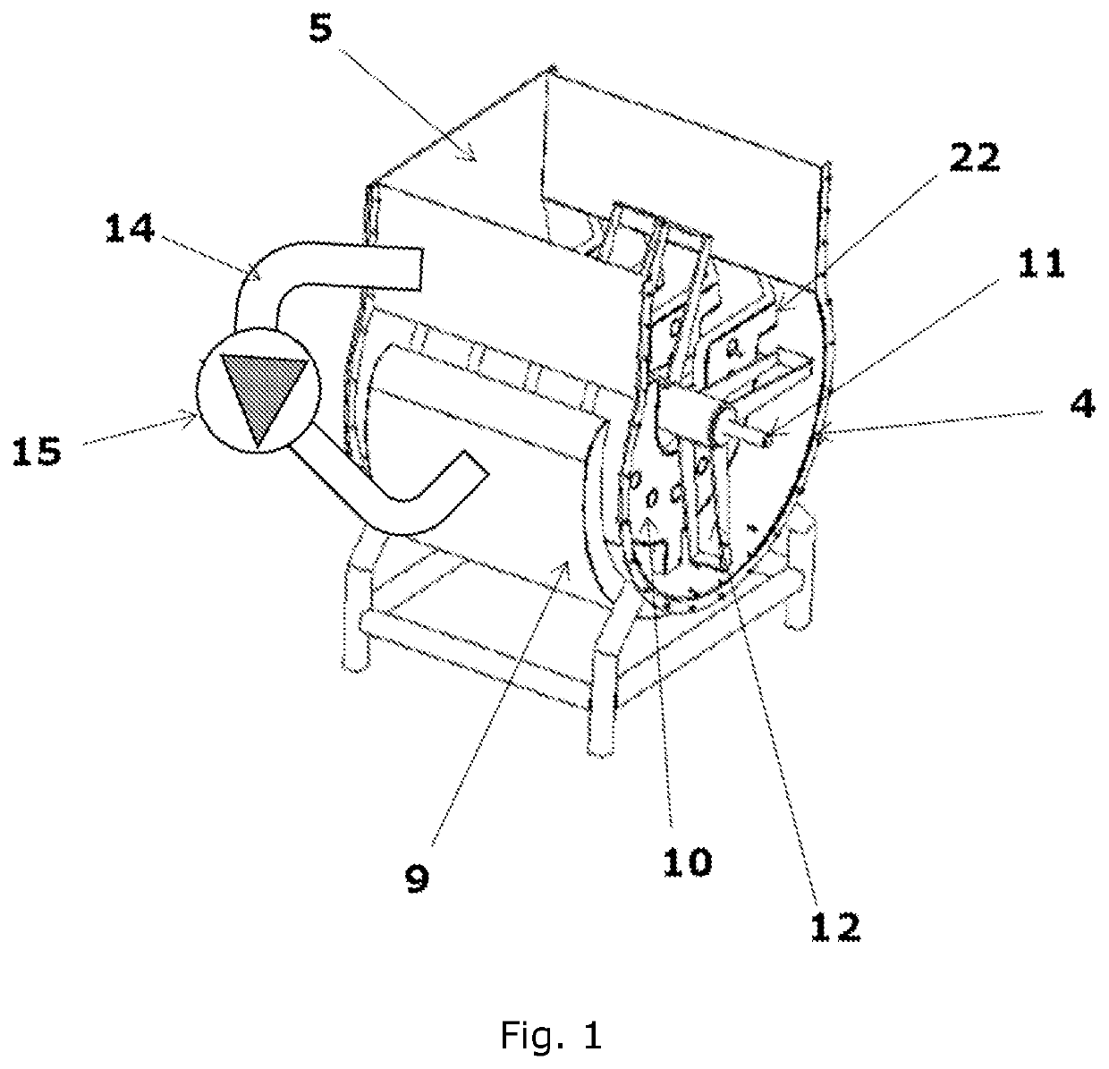
[0047]FIG. 1 shows a simplified embodiment of the MVR function, where a dryer has a sin...


PUM


Abstract

The present invention relates to a new device, a system and a method for both cooking and drying or removing the water phase from material. The device of the present invention has a large area for heat exchange and scrapers which stir the material in the container rather than transferring it around in circles.

Description

RELATED APPLICATIONS[0001]The present application is a U.S. National Stage application under 35 USC 371 of PCT Application Serial No. PCT / IS2017 / 050002, filed on 10 Feb. 2017; which claims priority from IS Patent Application No. 050142, filed 10 Feb. 2016, the entirety of both of which are incorporated herein by reference.FIELD[0002]The present invention relates to a new device for drying material, such as organic material. More specifically the present invention relates to a dryer apparatus with disks and scrapers for heat exchange and evaporation of the water phase from any material.INTRODUCTION[0003]Prior art steam dryers are generally designed as a cylinder having a steam heated jacket throughout and a steam heated rotor, with hollow flights on the rotor. Material sticking to heat exchange surfaces makes control of drying problematic. These devices need to be cleaned very frequently, which is time consuming and prevents continuous use.[0004]The problems with such device are insu...

Claims


Application Information

Patent Timeline
Patent Type & Authority Patents(United States)
IPC IPC(8): F26B3/24F26B23/00F26B11/16F26B25/04F26B17/20F26B3/18
CPCF26B3/24F26B3/18F26B23/004F26B17/205F26B25/04F26B11/16Y02P70/10Y02B30/52
Inventor PALSSON, GUNNAR
Owner HEDINN
Why Eureka
Try Eureka