Alignment system and method for a concrete truck at a concrete plant or a cement tanker at a cement loading station

a technology of cement loading station and cement plant, which is applied in the field of cement and concrete trucking, can solve the problems of difficult alignment of feed hopper to discharge chute, failure of alignment devices, camera, light system etc., and achieve the effect of improving the accuracy of the alignmen

Active Publication Date: 2020-10-13
FAULKNER GEORGE WAYNE
View PDF5 Cites 3 Cited by
  • Summary
  • Abstract
  • Description
  • Claims
  • Application Information

AI Technical Summary

Benefits of technology

The patent text describes a way to quickly understand the technical effects of a patent. It includes a table that groups together various features in different embodiments to make it easier to read. The text also mentions that the claimed embodiments may have more features than what is explicitly stated in the claims. The main technical effect is to provide a more efficient and organized way of disclosing inventive subject matter.

Problems solved by technology

The problem of aligning the feed hopper to the discharge chute is difficult because of the dust involved and a shroud often found around the discharge chute.
Similar alignment challenges can exist at cement plants due to the dust.
Several alignment devices, cameras, light systems etc. have failed.
For example video equipment that may normally be used to provide a visual image to help with alignment cannot be used if mounted outside the shroud because the shroud cannot be seen through, even if the shroud is made of clear material it will soon be covered in dust and no image of the discharge chute and feed hopper can be provided.
If instead the concrete plant would mount the camera inside the shroud that camera lens would quickly get covered with dust and again become inoperative.

Method used


Image

  • Alignment system and method for a concrete truck at a concrete plant or a cement tanker at a cement loading station
  • Alignment system and method for a concrete truck at a concrete plant or a cement tanker at a cement loading station
  • Alignment system and method for a concrete truck at a concrete plant or a cement tanker at a cement loading station

Examples


Embodiment Construction

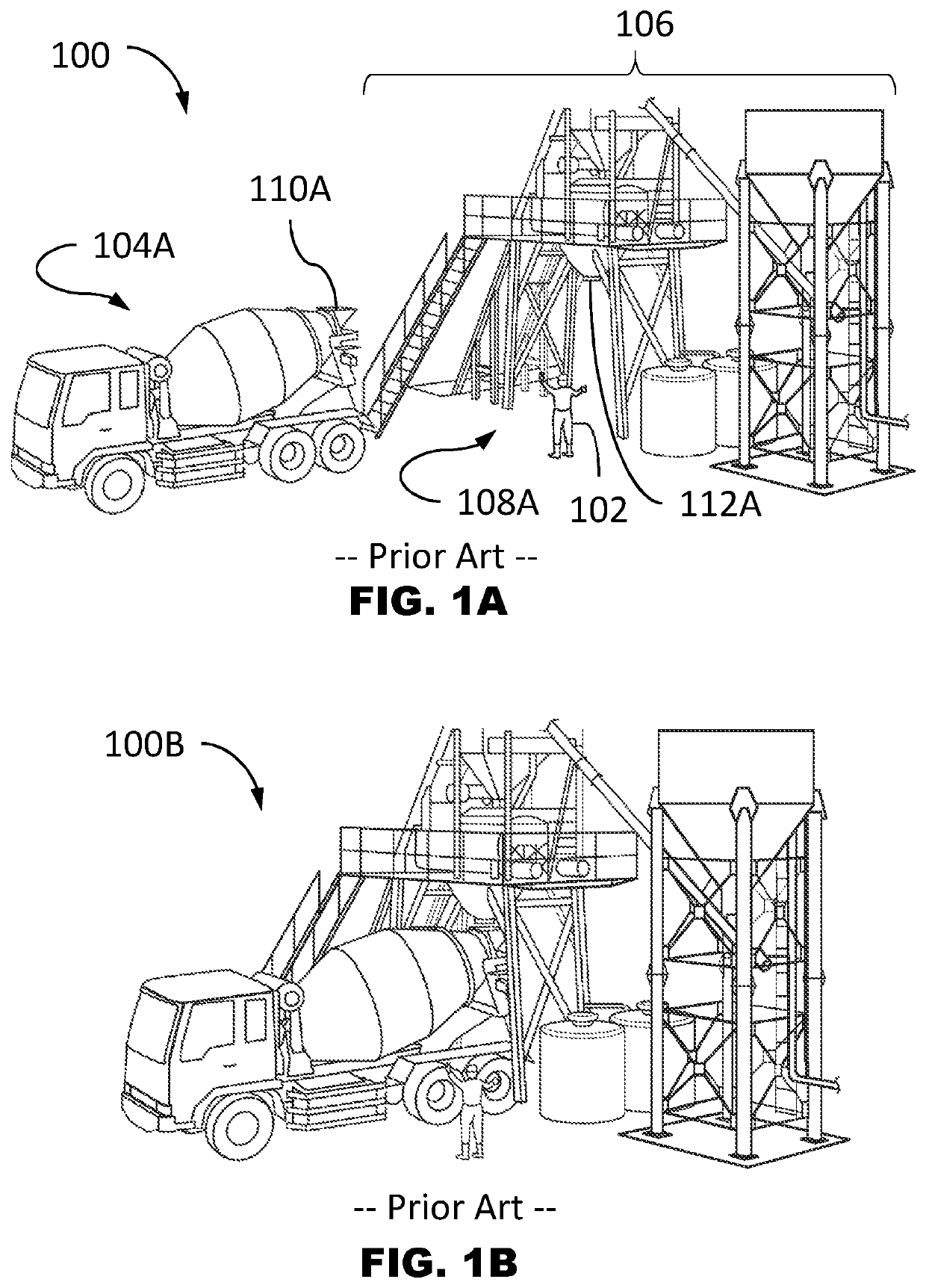
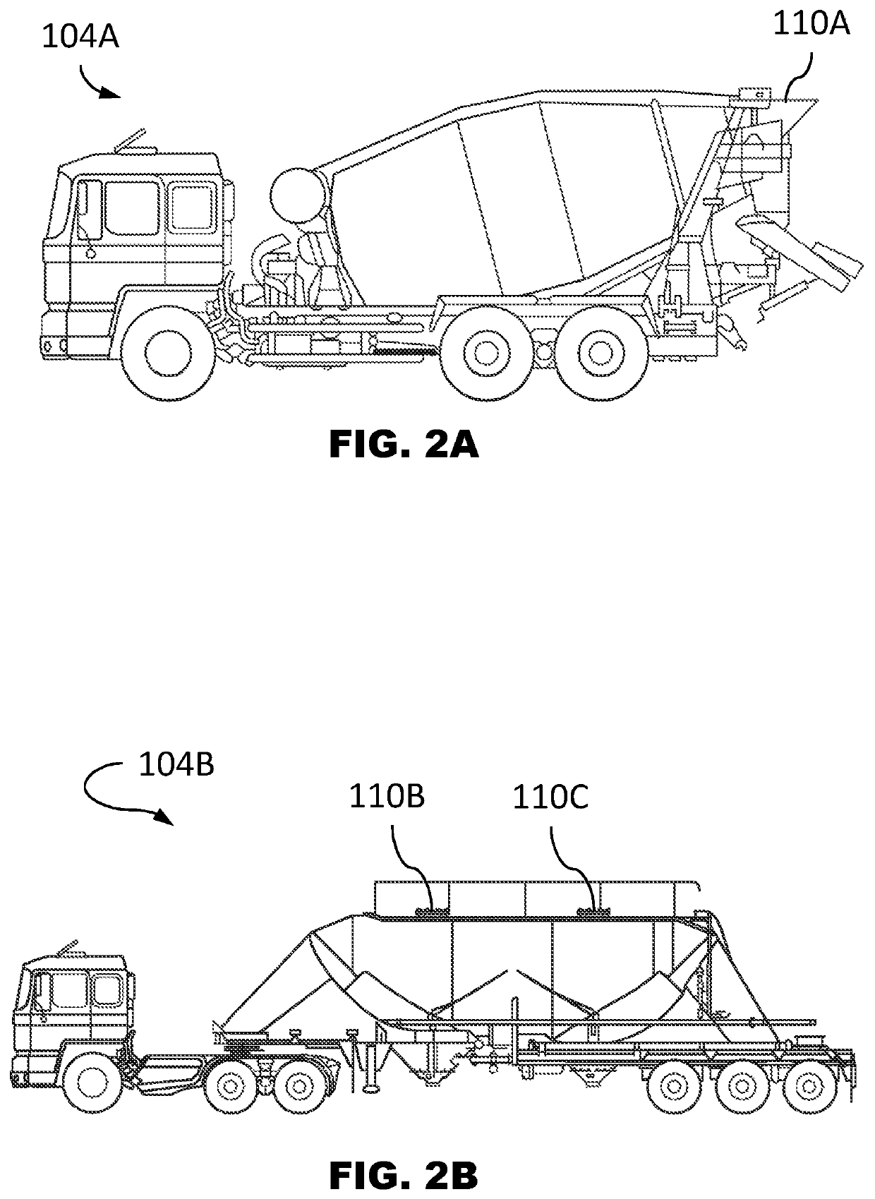
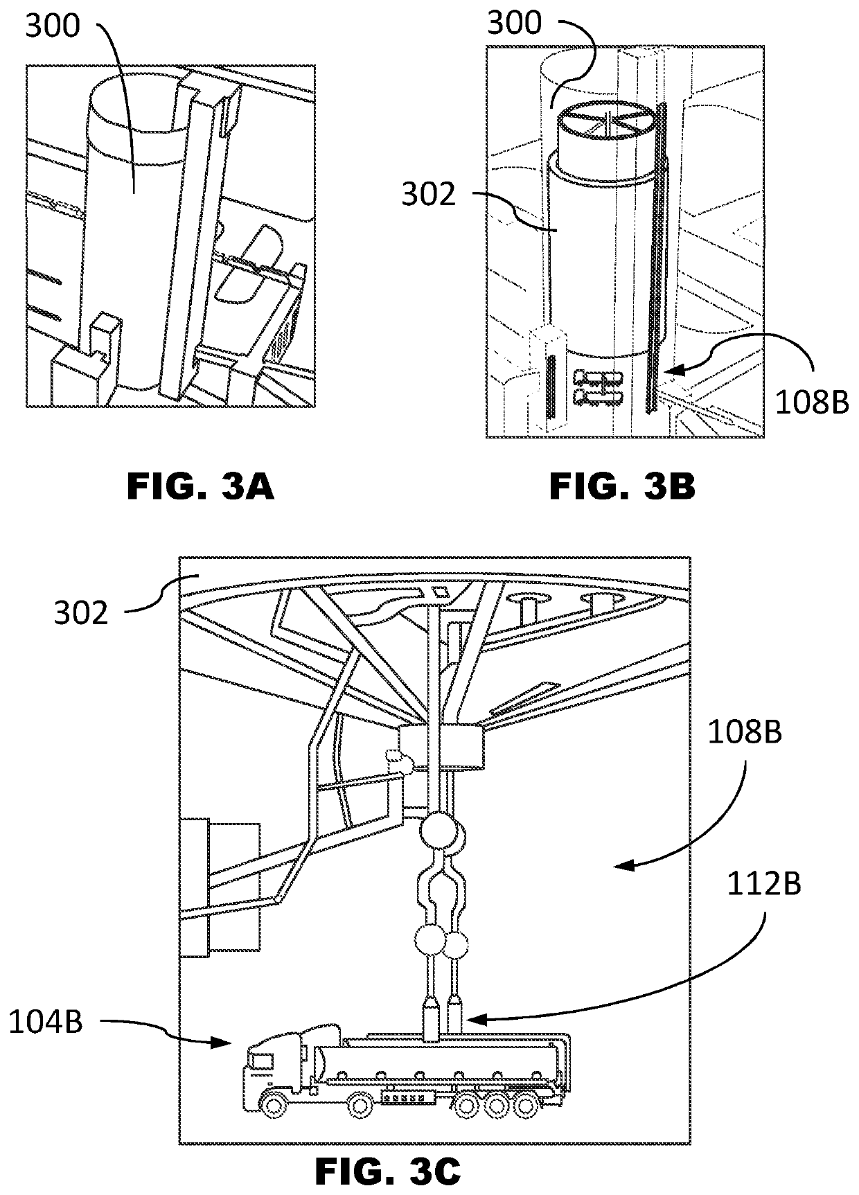
[0024]FIG. 1A depicts a scene 100 of the prior art of a dedicated person 102 helping backup a concrete mixer truck 104A at a concrete plant 106 to a concrete loading station 108A. The concrete mixer truck 104A has a feed hopper 110A that should align to a concrete discharge chute 112A of the concrete loading station 108A.

[0025]FIG. 1B depicts a scene 100B of the prior art after the concrete truck 104B has been successfully backed-up and aligned to the concrete loading station 108A so that the feed hopper 110A and the concrete discharge chute 112A are aligned. In the aligned configuration the material (e.g. concrete) can move from the concrete discharge chute 112A into the feed hopper 110A of the concrete mixer truck 104A. If the feed hopper 110A is not properly aligned to the concrete discharge chute 112A, then when the material is released the materials will spill on the ground and not arrive in the truck mixing chamber. This will waste materials, and if this is a dry mix plant the...


PUM


Abstract

A concrete truck or cement tanker truck alignment system with a loading station having a discharge chute, an electronic sensor that sees through dust or an environmental dust shield, and provides location information used to determine a hopper offset. The hopper offset is a measurement of the physical offset between a feed hopper on the truck and the discharge chute. The system may further include an alignment feedback unit that provides feedback based on the hopper offset. The alignment feedback unit may indicate the hopper offset is within an alignment tolerance. The sensor may use radar. The alignment feedback unit may provide auditory or graphical feedback. The graphical feedback may show a discharge icon representing the position of the discharge chute and a hopper icon representing the feed hopper where the location of the hopper icon is relative to the discharge chute based on the hopper offset.

Description

CROSS-REFERENCE TO RELATED APPLICATION[0001]This application claims the benefit of U.S. Provisional Application No. 62 / 984,808, filed Mar. 4, 2020.BACKGROUND OF THE INVENTIONField of the Invention[0002]The invention relates generally to the cement and concrete trucking industry, more particularly, to a system and method to help position trucks so a feed hopper on a concrete truck is aligned to the discharge chute at a concrete plant and the inlet hole of a cement tanker is aligned to the discharge chute at a cement plant.Background of the Invention[0003]In the cement industry the dry powder cement originates from a big cement factory. At the cement factory there are cement terminals where the dry powder cement is stored in large overhead silos that a cement transport tanker (also known as a cement hauler truck or cement tanker) will drive under and align the inlet hatch to a discharge chute that fills the cement tanker with dry powder cement. The cement tanker may take the dry powde...

Claims


Application Information

Patent Timeline
IPC IPC(8): G01S13/06G01S13/88B65G65/00G01S13/04B65G67/06B65G69/00
CPCB65G67/06G01S13/04B65G69/006B65G65/005G01S13/88B65G2814/0323B65G2203/042B65G69/2882B60P3/16B28C5/4237B28C5/4206B28C7/0481
Inventor FAULKNER, GEORGE WAYNE
Owner FAULKNER GEORGE WAYNE
Why Eureka
Try Eureka