
Method and device for controlling the oil temperature of an oil-injected compressor installation or vacuum pump using a flow distributor

Active Publication Date: 2020-10-20
ATLAS COPCO AIRPOWER NV
View PDF14 Cites 0 Cited by
  • Summary
  • Abstract
  • Description
  • Claims
  • Application Information

AI Technical Summary

Benefits of technology

The invention relates to a device that recovers energy from waste heat. The advantage of the device is that it includes a cooler that is placed in parallel with the energy recovery system. This allows the oil to be cooled directly without first passing through the energy recovery system when it is hot. The device also ensures that the oil supply to the compressor element is always maintained, which is important for lubrication and cooling.

Problems solved by technology

With an oil-injected compressor installation, the lubrication and cooling oil that is injected into the compressor installation can consequently become contaminated with condensate, which often leads to the degradation of this oil and wear of the various components of the compressor installation.
Moreover, the condensate can also cause corrosion in the compressor installation.
However, it must always be considered that the temperature in the compressor element and the underlying components at the outlet may not be too high, as too high a temperature causes a degradation of the cooling and lubrication properties of the oil.
A disadvantage of such a device is that the heat that is removed by the cooler of the system cannot be usefully utilised.
A disadvantage of such devices is that they require a complex and sizeable system with thermostatic valves.
An additional disadvantage of such thermostatic valves is that they can only switch at one temperature and consequently cannot respond to changes of the dew point.
Another disadvantage of such known devices is that the cooler and the energy recovery system are in series with one another, i.e. all oil that passes through the cooler also passes through the energy recovery system.
However, the cooler is not equipped for this so that the oil can be insufficiently cooled, with the aforementioned detrimental consequences as a result.

Method used


Image

  • Method and device for controlling the oil temperature of an oil-injected compressor installation or vacuum pump using a flow distributor
  • Method and device for controlling the oil temperature of an oil-injected compressor installation or vacuum pump using a flow distributor
  • Method and device for controlling the oil temperature of an oil-injected compressor installation or vacuum pump using a flow distributor

Examples


Embodiment Construction

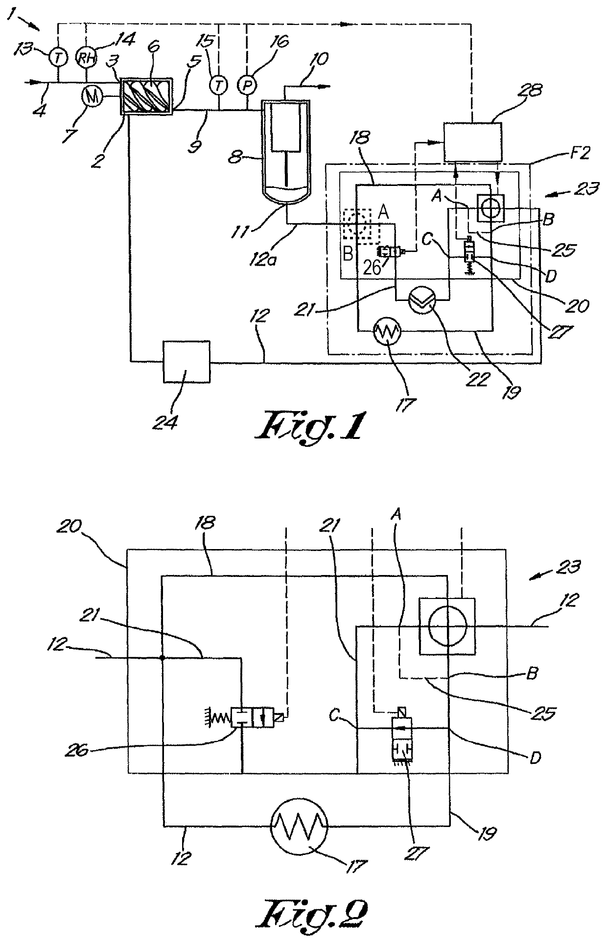
[0049]The oil-injected compressor installation 1 shown in FIG. 1 comprises an oil injected compressor element 2 that is provided with a gas inlet 3 with an inlet pipe 4 and an outlet 5 for compressed gas.

[0050]In this case the compressor element 2 is a screw compressor element with two meshed helical rotors 6 that are driven by means of a motor 7.

[0051]The aforementioned outlet 5 is connected to an oil separator 8 by means of a pressure pipe 9.

[0052]The oil separator 8 comprises a gas outlet 10, along which the purified and compressed gas can be carried to a pressure network or to consumers of compressed gas such as pneumatic tools for example.

[0053]The oil separator 8 also comprises an oil outlet 11 to be able to carry away the separated oil, whereby this oil outlet 11 is connected to an injection pipe 12 via an oil pipe 12a to be able to inject the oil back into the compressor element 2.

[0054]At the location of the inlet 3, in this case in the inlet pipe 4, means 13 respectively 1...


PUM


Abstract

A device for controlling the oil temperature of an oil-injected compressor installation with a compressor element that is provided with a gas inlet and an outlet for compressed gas that is connected to an oil separator that is connected by an injection pipe to the compressor element. A cooler is affixed in a part of the injection pipe that can be bypassed by means of a bypass pipe. The device is also provided with an extra pipe that is intended to be connected in parallel with the bypass pipe and the cooler, and in which an energy recovery system can be connected. Additionally, the device is provided with a flow distributor through the cooler, the bypass pipe and the extra pipe, and a controller for controlling these temperature control devices at the outlet of the compressor element.

Description

[0001]The present invention relates to a method and device for controlling the oil temperature of an oil-injected compressor installation or vacuum pump.[0002]More specifically, the invention is intended to prevent the formation of condensate in compressed gas originating from an oil-injected compressor installation and to keep the oil temperature closer above the actual dew point.BACKGROUND OF THE INVENTION[0003]The invention can also be applied to vacuum pumps. After all, a vacuum pump is in fact a compressor installation whose input is connected to the vacuum pipe, reservoir or similar to be drawn.[0004]Oil-injected compressor installations are already known that comprise a compressor element that is provided with a gas inlet and outlet for compressed gas, which is connected to an oil separator that is connected by means of an injection pipe to the aforementioned compressor element and whereby a cooler is affixed in the injection pipe that can be bypassed by means of a bypass pip...

Claims


Application Information

Patent Timeline
IPC IPC(8): F04C29/00F16K11/08F04C29/02F04C29/04
CPCF04C29/04F04C29/0014F04C29/026F16K11/08F04C2270/44F04C2270/195F04C2270/18
Inventor DE VOCHT, KENNETHDESIRON, ANDRIES JAN F.
Owner ATLAS COPCO AIRPOWER NV
Learn More