Extruded housing for electric motor

a technology of extruded housing and electric motor, which is applied in the direction of dynamo-electric machines, magnetic circuit rotating parts, magnetic circuit shape/form/construction, etc., to achieve the effect of reducing the cost of the devi

Active Publication Date: 2020-10-20
GOODRICH ACTUATION SYST
View PDF20 Cites 0 Cited by
  • Summary
  • Abstract
  • Description
  • Claims
  • Application Information

AI Technical Summary

Benefits of technology

[0007]The inventors have realised that whilst the extruded arrangement of FIG. 2 provides substantial benefits in costs in comparison to the machined housing with radial fins shown in FIG. 1, there is also a significant disadvantage when it is necessary to use the motor housing in a horizontal orientation. The axial fins have been found to be highly inefficient in dissipating heat by natural convection in this orientation. FIGS. 3 and 4 show a comparison of the thermal performance for the radial fin and the axial fin designs. The difference in performance is very much higher than might be expected. The radial fin housing temperature peaks at 105° C., whilst the axial fin housing rises by a further 115° C. to a peak of 220° C. By incorporating radial cuts via machining after the extrusion then the efficiencies lost with axial fins may be recovered. Thus, the inventors have found that a relatively simple post extrusion machining process results in a surprisingly large increase in performance. The performance gain far exceeds any disadvantage arising from the cost of the additional machining. The cost for manufacture of a housing as in the first aspect will be about 10-25% of the cost of manufacture for a fully machined housing of similar thermal performance. The proposed housing may also be used in either a vertical or a horizontal orientation with good thermal performance.

Problems solved by technology

The housing 12 of FIG. 1 provides a good performance in terms of heat dissipation, but it is expensive as a large amount of machining time is required in order to produce the radial fins, and since the machining operation generates a significant amount of waste material.
The inventors have realised that whilst the extruded arrangement of FIG. 2 provides substantial benefits in costs in comparison to the machined housing with radial fins shown in FIG. 1, there is also a significant disadvantage when it is necessary to use the motor housing in a horizontal orientation.

Method used


Image

  • Extruded housing for electric motor
  • Extruded housing for electric motor
  • Extruded housing for electric motor

Examples


Embodiment Construction

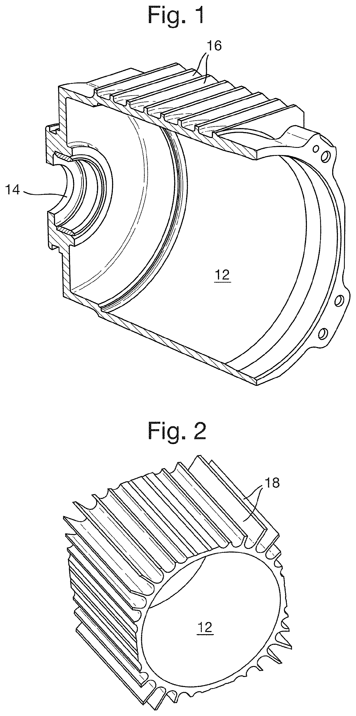
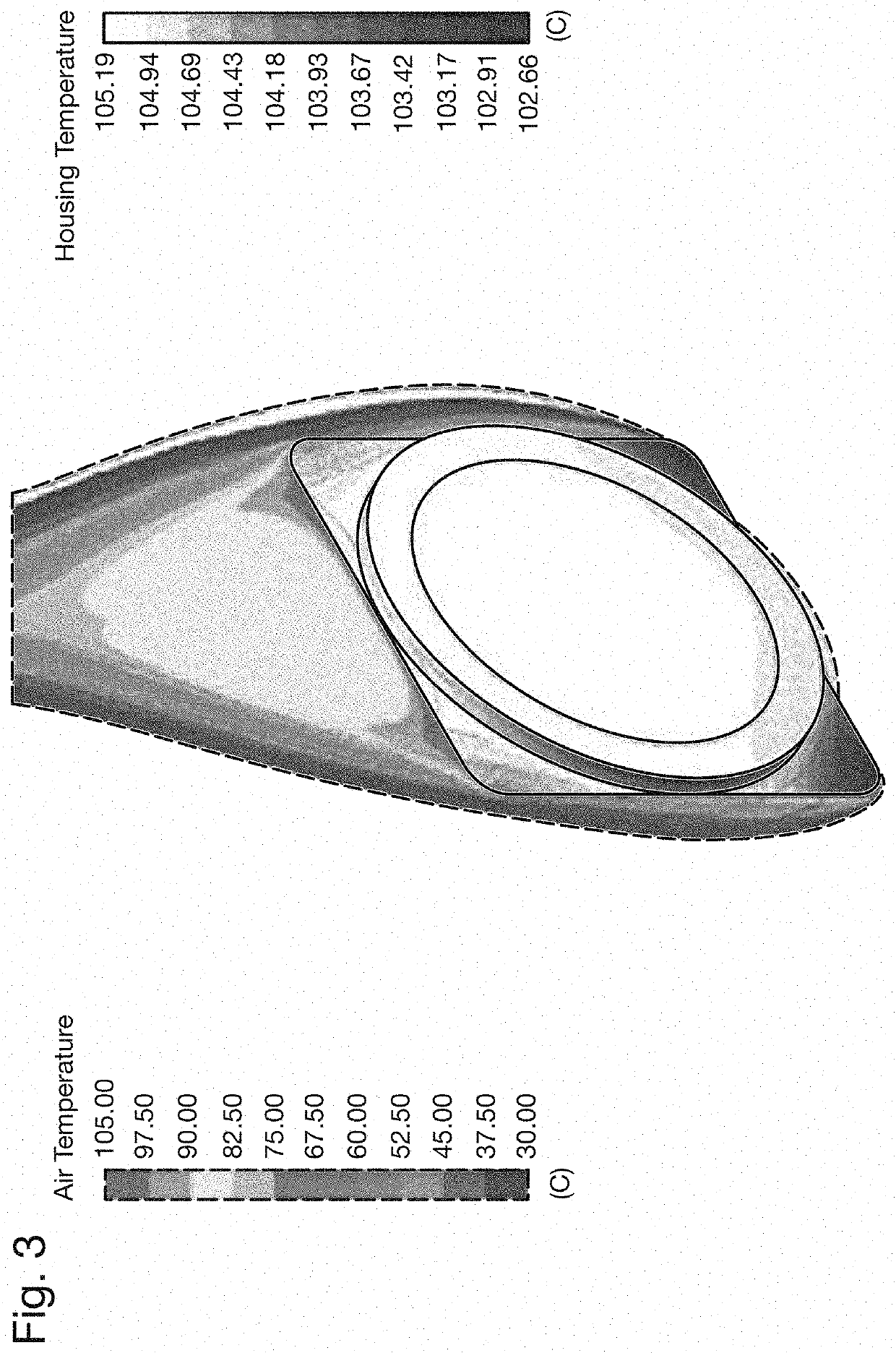
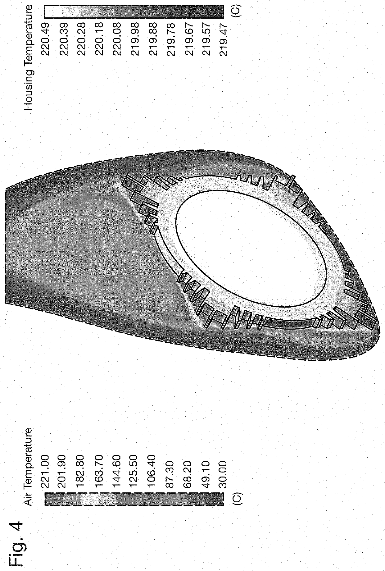
[0024]The prior art housings of FIGS. 1 and 2, and the thermal performances shown in FIGS. 3 and 4 have been discussed above. FIG. 5 shows a proposed extruded motor housing 12 with axial fins 18 having radial cuts 20 extending circumferentially around the external surface of the housing 12. This extruded motor housing 12 may be formed by an extrusion process similar to that used for the housing 12 of FIG. 2, followed by a machining step where the radial cuts 20 are machined using a lathe or other machine tool. The use of a lathe allows for quick and effective machining of radial cuts into a rotationally symmetric component such as the motor housing 12. The motor housing 12 also includes a bearing support 14, which can be separately manufactured and then mounted to the cylindrical body of the housing 12 via any suitable means, for example via friction fit, brazing or welding.

[0025]As can be seen by a comparison of the thermal performance shown in FIG. 6 with the thermal performance s...


PUM


Abstract

An extruded housing for an electric motor comprises: an extruded cylindrical body for holding electrical parts of the motor, extruded axial fins formed about the outside of the cylindrical body, and radial cuts machined through the axial fins.

Description

FOREIGN PRIORITY[0001]This application claims priority to European Patent Application No. 15178844.5 filed Jul. 29, 2015, the entire contents of which is incorporated herein by reference.TECHNICAL FIELD[0002]The invention relates to an extruded housing for an electric motor and to a related method of manufacturing a housing for an electric motor, for example for an aerospace electric motor.BACKGROUND OF THE INVENTION[0003]Electric motors, in general terms, consist of moving and stationary parts forming a rotor and stator of an electrical machine, with these parts being enclosed in a housing. The housing acts to protect the moving parts, and in addition may have the function of dissipating heat that is produced by the motor. The dissipation of heat is of particular importance in high performing motors and / or in motors that are intended to be used where there are restrictions on the space and orientation required for installation of the motor. It is also of particular importance when ...

Claims


Application Information

Patent Timeline
Patent Type & Authority Patents(United States)
IPC IPC(8): H02K1/32H02K15/14H02K5/18
CPCH02K15/14H02K5/18
Inventor HARRIS, PAUL CHARLESPOCOCK, EDWARD GRAHAM CHARLESCLAYCOMB, CHRIS H. A.
Owner GOODRICH ACTUATION SYST
Why Eureka
Try Eureka