
Cascade-type hybrid energy cell

a hybrid energy cell and cascade-type technology, applied in the field of cascade-type hybrid energy cells, can solve the problems of significant solar energy, greater non-radiative recombination across, and undercutting these advantages, so as to improve the piezoelectric voltage output of the checs, effective combined energy harvesting, and the effect of strong voltage drop

Active Publication Date: 2020-10-27
SHIMCO NORTH AMERICA INC
View PDF4 Cites 0 Cited by
  • Summary
  • Abstract
  • Description
  • Claims
  • Application Information

AI Technical Summary

Benefits of technology

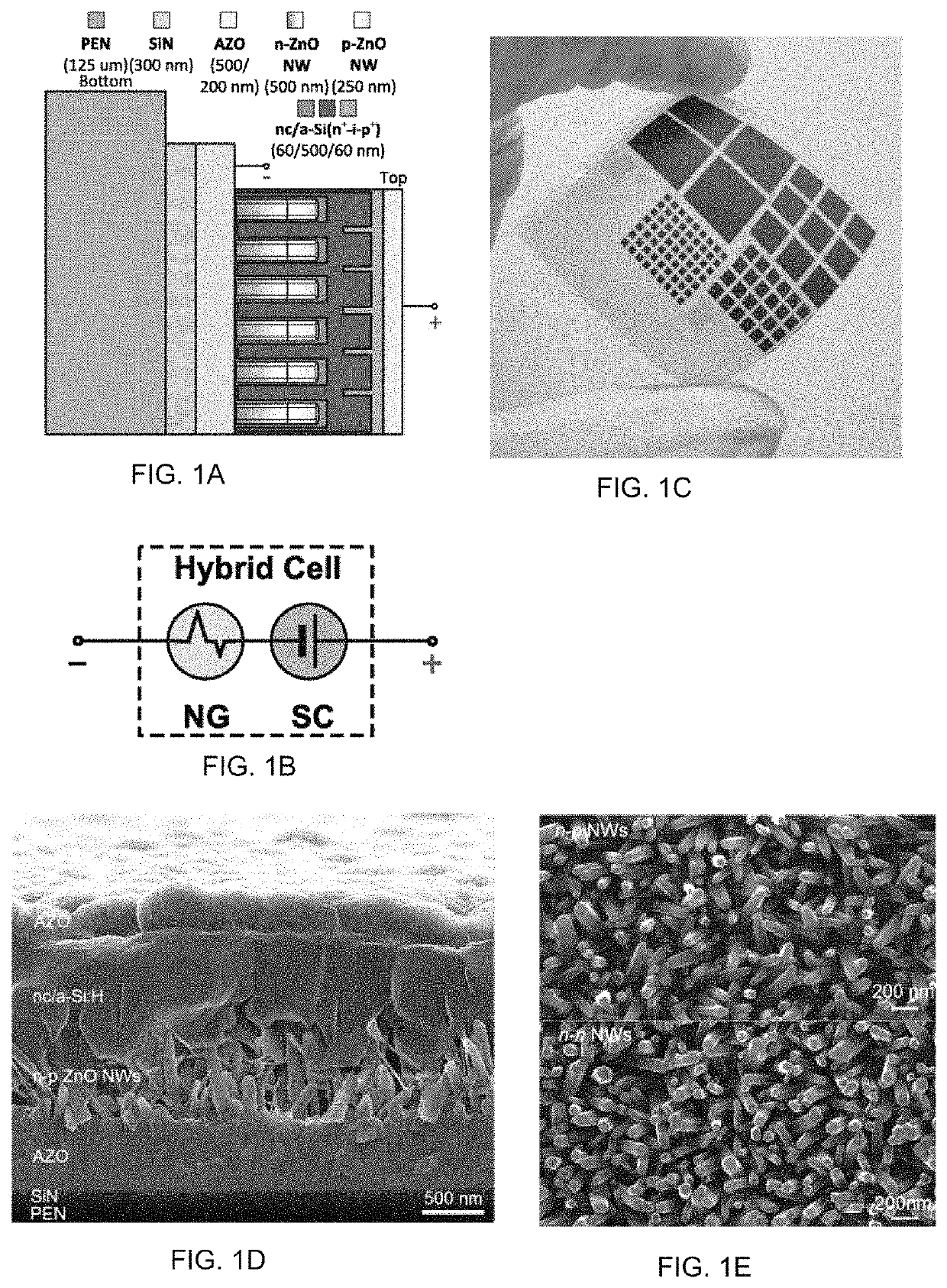
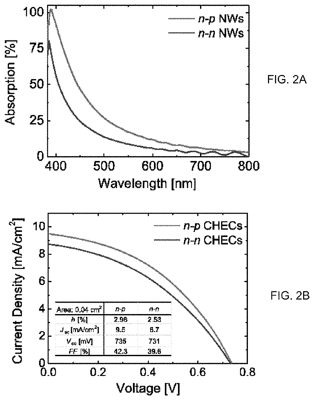
[0019]Thus, the present inventors have developed a novel CHEC. In a highly preferred embodiment, the CHEC is first cascade-type transparent vibration / solar energy cell synthesized on a polyethylene naphthalate (PEN) flexible substrate. This cascade-type CHEC monolithically-integrated two-terminal structure substantially suppresses the large interfacial electrical losses typically encountered in mechanically stacked devices. Furthermore, integrating the solar cell on top of the piezoelectric nanogenerator significantly enhances output power density, through effective, simultaneous and complementary harvesting of ambient strain and solar energies. In a preferred embodiment, the present CHEC consists of a vertically-aligned n-p ZnO homojunction NW-based nanogenerator and a hydrogenated nanocrystalline / amorphous silicon (nc / a-Si:H) n+-i-p+ junction solar cell. The full inorganic heterostructure of this preferred embodiment of the present CHEC improves chemical stability and mechanical durability. It is believed that the present CHEC can, for example, function as a sensor, a solar cell, a nanogenerator and the like.
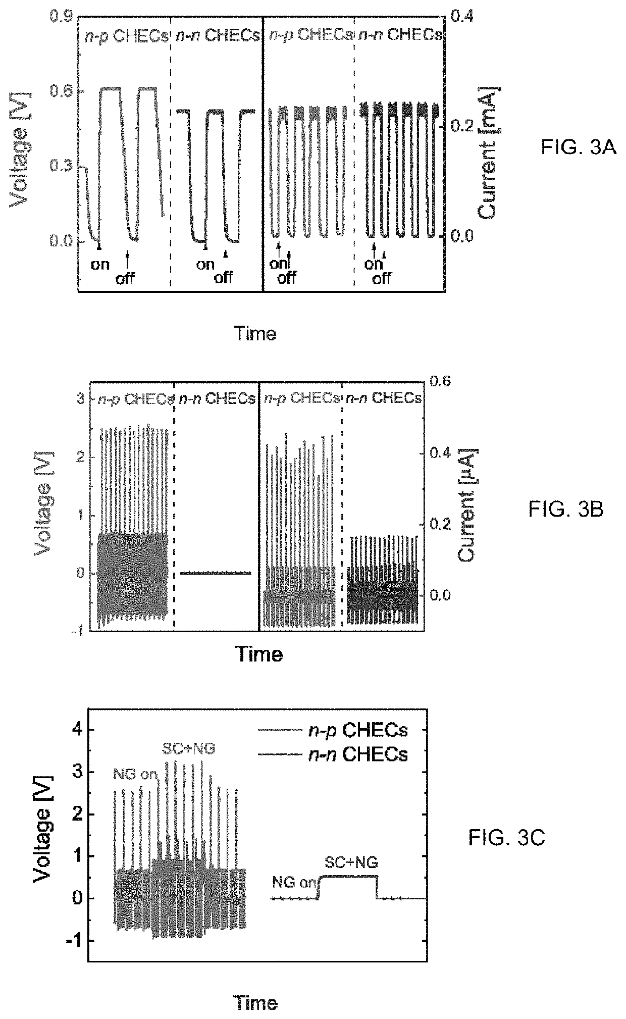
[0021]In a preferred embodiement mploying n-p junction based ZnO nanowires in the nanogenerator component improves the piezoelectric voltage output of the CHECs by more than two orders of magnitude (138 times). Under indoor ambient illumination and mechanical excitation with an acceleration of 3 m / s2 at 3 Hz frequency, the output current and voltage from a single 1.0 cm2-sized n-p junction-based CHEC were found to be 280 μA and 3.0 V, respectively—enough to drive low-power commercial electronics. Six such CHECs connected in series to charge a capacitor harnessed enough energy to light up 8 blue and 3 white LEDs in pulsed mode or to drive a wireless strain gauge sensor node intermittently.
[0023]The present CHEC can be used to exploit piezopotential under compressive strain and photovoltaic potential under ambient optical illumination, to generate electrical power. The CHECs, when placed solely under optical illumination, function as traditional solar cells and produce continuous photocurrent output. The photocurrent flows from the solar cell component. When a compressive force is applied, negative piezopotential (V−) is generated at the one interface (bottom) and positive piezopotential (V+) at the other interface (the top) of the nanogenerator layers. The photovoltaic potential and the piezopotential are in the same direction and thus the generated electrical power add on together. The combined potential creates a stronger voltage drop between the positive (top) port and the negative (bottom) port, which drives current through an external load.
[0024]The buffer layer (such as SiN) improves the surface properties of the substrate.
[0028]The above-mentioned laminate structure is is encapsulated by an encapsulation element. Preferably, the encapsulation element substantially completely encompasulates the laminate structure. One non-limiting example of the encapsulation layer is PDMS, Dow Corning Sylgard™ 184 premixed with curing agent at a ratio of 10:1 w / w and degassed, to prevent contamination, damage, and moisture penetration from the ambient environment.

Problems solved by technology

However, vibrations generate power only while motion persists and solar energy is significant only when optical illumination is sufficient.
On the other hand, the increased surface area in high aspect-ratio NW structures may also cause greater non-radiative recombination across local junctions / interfaces due to surface defects, which often undercuts these advantages [30-32].

Method used


Image

  • Cascade-type hybrid energy cell
  • Cascade-type hybrid energy cell
  • Cascade-type hybrid energy cell

Examples


Embodiment Construction

[0048]The present invention relates to a cascade-type hybrid solar and piezoelectric (and / or triboelectric, and / or thermoelectric) nanogenerator comprising a laminate structure having the following elements: (a) a substrate; (b) an electrically insulating buffer layer; (c) a first electrode element; (d) a piezoelectric (and / or triboelectric, and / or thermoelectric) element configured to convert mechanic (and / or thermal) energy to electrical energy; and (e) a solar cell element configured to convert optical energy to electrical energy; and (f) a second electrode element; wherein the nanogenerator further comprises an encapsulation element that encapsulates the laminate structure.

[0049]Preferred embodiments of this cascade-type hybrid solar and piezoelectric (and / or triboelectric, and / or thermoelectric) nanogenerator may include any one or a combination of any two or more of any of the following features:[0050]the substrate is a polymer;[0051]the substrate is a non-polymeric material;[...


PUM

PropertyMeasurementUnit
temperatureaaaaaaaaaa
voltageaaaaaaaaaa
frequencyaaaaaaaaaa

Abstract

There is described a cascade-type compact hybrid energy cell (CHEC) that is capable of individually and concurrently harvesting solar, strain and thermal energies. The cell comprises an n-p homojunction nanowire (NW)-based piezoelectric nanogenerator and a nanocrystalline / amorphous-Si:H single junction cell. Under optical illumination of ˜10 mW / cm2 and mechanical vibration of 3 m / s2 at 3 Hz frequency, the output current and voltage from a single 1.0 cm2-sized CHEC was found to be 280 μA and 3.0 V, respectively—this is are sufficient to drive low-power commercial electronics. Six such CHECs connected in series were found to generate enough electrical power to light emitting diodes or drive a wireless strain gauge sensor node.

Description

CROSS-REFERENCE TO RELATED APPLICATION[0001]The present application claims the benefit under 35 U.S.C. § 119(e) of provisional patent application Ser. No. 62 / 602,895, filed May 11, 2017 and the benefit under 35 U.S.C. § 119(a) Canadian patent application 2,967,004, filed May 11, 2017, the contents of which are hereby incorporated by reference.BACKGROUND OF THE INVENTIONField of the Invention[0002]In one of its aspects, the present invention relates to a Cascade-type Hybrid Energy Cell (CHEC).Description of the Prior Art[0003]Solar [1-5] and vibration [6-8] energies are most commonly available in the ambient environment. They can be harvested, converted into electrical energy and used to operate autonomous wireless sensor networks (WSNs) [9]. However, vibrations generate power only while motion persists and solar energy is significant only when optical illumination is sufficient. Thus, a technology that can harvest energy from both sources would produce more reliable and substantial ...

Claims


Application Information

Patent Timeline
Patent Type & Authority Patents(United States)
IPC IPC(8): H01L31/075H02N1/04H02N2/18H01L41/053H01L41/047H01L35/24H01L41/18H02S10/10H01L31/048H01L41/29H01L27/16H01L31/0352H01L31/0392H01L29/06H01L31/046H01L27/142H01L35/32H01L35/14H01L31/18H01L41/113
CPCH01L35/24H01L31/035281H01L41/29H01L31/046H01L27/142H01L31/03926H01L31/03921H01L29/0669H01L31/1884H01L41/053H02S10/10H01L41/18H01L41/0478H01L41/1136H01L27/16H01L35/32H01L35/14H01L41/113H02N1/04H02N2/18H01L31/075H01L31/0481Y02E10/548H10N19/00H10N10/851H10N10/856H10N10/17H10N30/878H10N30/30H10N30/06H10N30/85H10N30/88H10N30/306
Inventor BAN, DAYANLIU, GUOCHENG
Owner SHIMCO NORTH AMERICA INC
Learn More