Gas diffusion electrode

a technology of gas diffusion electrode and fuel cell, which is applied in the direction of fuel cells, cell components, fused electrolyte fuel cells, etc., can solve the problems of difficult to achieve both the anti-flooding characteristic and the anti-drying characteristic, and achieve high fuel cell performance, good water removal performance, and high gas diffusivity

Active Publication Date: 2020-10-27
TORAY IND INC
View PDF67 Cites 0 Cited by
  • Summary
  • Abstract
  • Description
  • Claims
  • Application Information

AI Technical Summary

Benefits of technology

[0012]Furthermore, for the popularization of a fuel cell or a fuel cell vehicle, it is essential to produce a high-performing fuel cell at a low cost. The lower cost for all the fuel cell members is thus required, including the gas diffusion electrode. The present invention provides a gas diffusion electrode which overcomes the above drawbacks of the prior art, achieves both the anti-dry-out characteristic and anti-flooding characteristic, shows good fuel cell performance as a gas diffusion electrode, and is low in cost.
[0025]The use of the gas diffusion electrode of the present invention can provide a low-priced fuel cell which shows high gas diffusivity, good water removal performance, and high fuel cell performance in a wide temperature range thanks to the achievement of both the anti-flooding characteristic and anti-dry-out characteristic.

Problems solved by technology

However, with the techniques disclosed in the above Patent Documents 1 to 5, it was difficult to achieve both the anti-flooding characteristic and the anti-dry-out characteristic, and to assure high performance in a wide temperature range for the application that requires a large output such as in the one installed in a fuel cell vehicle.

Method used


Image

  • Gas diffusion electrode
  • Gas diffusion electrode
  • Gas diffusion electrode

Examples


example 1

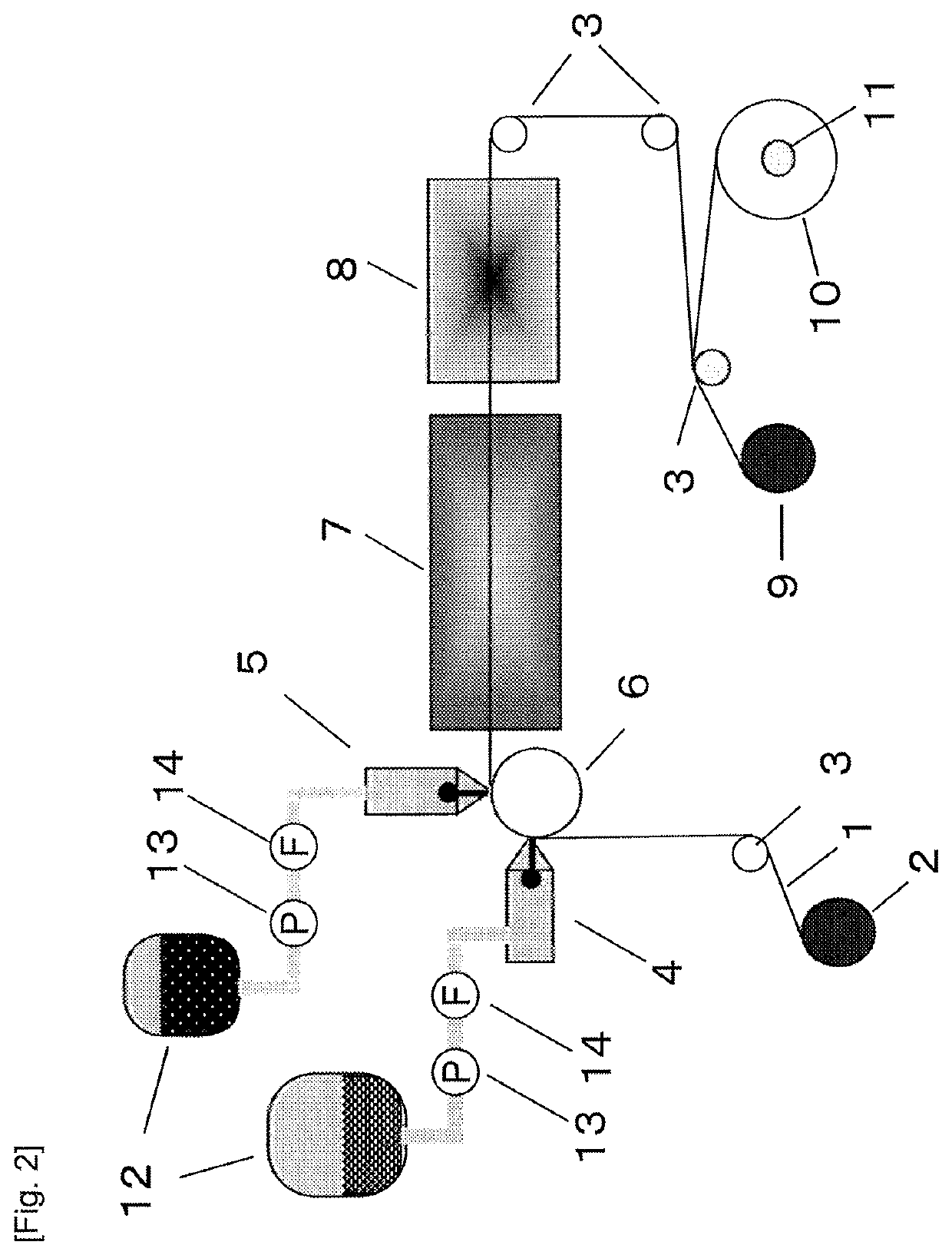
[0123]A carbon paper which was wound in a roll shape and had the thickness of 150 μm and the porosity of 85% was transported using a winding type transportation apparatus. During the transportation, the carbon paper was dipped in a dipping tank filled with a hydrophobic polymer dispersion in which a fluororesin was dispersed in water at the fluororesin concentration of 2% by mass and thus subjected to a hydrophobic treatment. Then the carbon paper was dried in the drying furnace 7 set at 100° C. and wound by a winder. Thus, an electrical conducting porous substrate subjected to a hydrophobic treatment was obtained. As the hydrophobic polymer dispersion, a FEP dispersion ND-110 in which FEP was diluted with water to the concentration of 2% by mass was used.

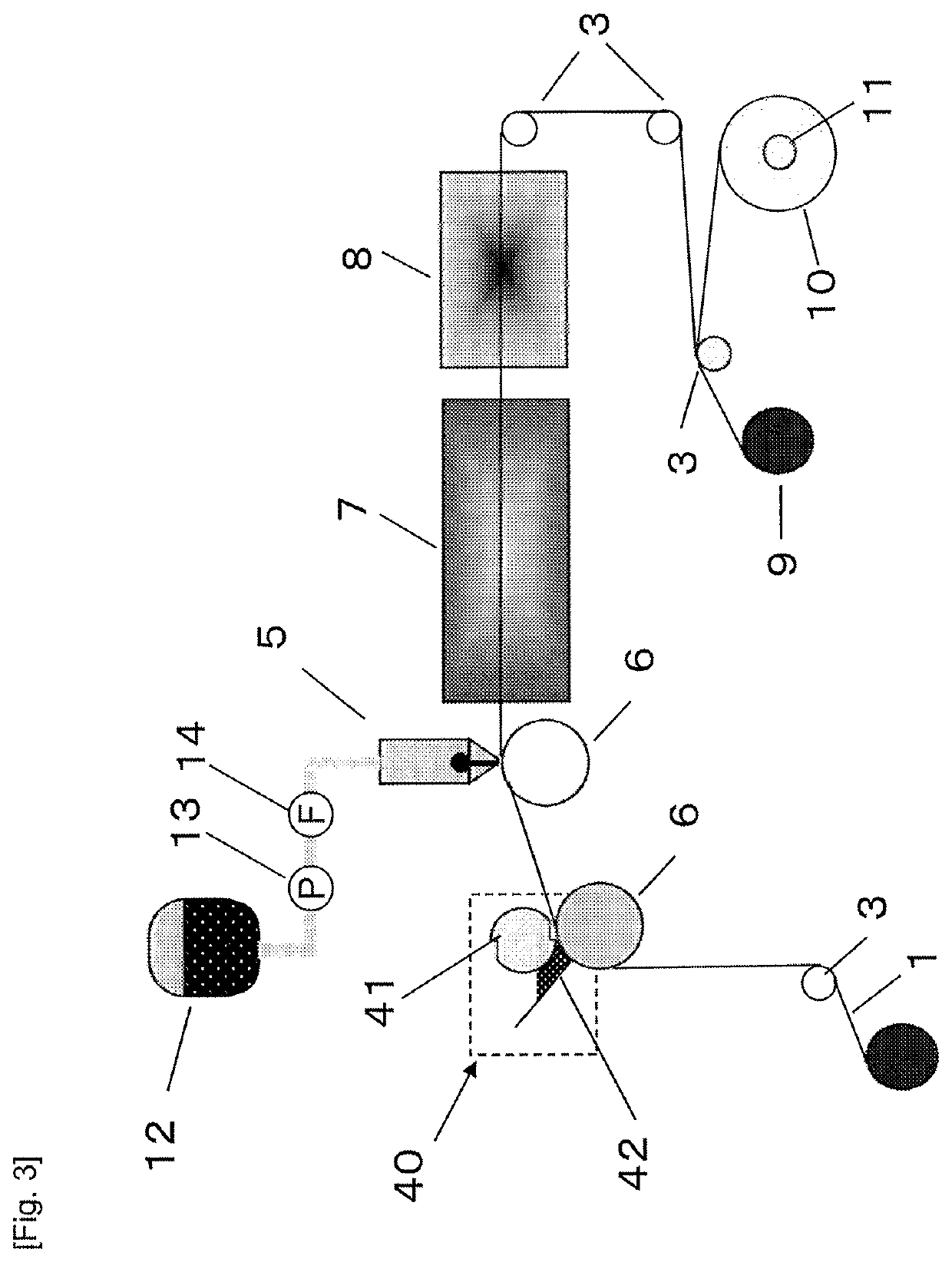
[0124]Then, as shown in the scheme of FIG. 2, a winding type continuous coater was prepared by providing the transportation apparatus equipped with the unwinder 2, the guide roll 3, the back roll 6, the interleave paper unwinder 11...

example 2

[0133]A gas diffusion electrode was obtained in the same way as in Example 1 except that the carbon black contained in the first ink in Example 1 was changed to the carbon black CB2 having a structure index of 3.0 or more.

example 3

[0134]A gas diffusion electrode was obtained in the same way as in Example 1 except that the thickness of the carbon paper in Example 1 was changed to 180 μm.


PUM

PropertyMeasurementUnit
pore size distributionaaaaaaaaaa

Abstract

A gas diffusion electrode has a microporous layer on at least one surface of an electrical conducting porous substrate. The microporous layer has at least a first microporous layer in contact with the electrical conducting porous substrate, and a second microporous layer. The gas diffusion electrode has a pore size distribution with a peak at least in a first region of 10 μm or more and 100 μm or less, a second region of 0.2 μm or more and less than 1.0 μm, and a third region of 0.050 μm or more and less than 0.2 μm. The total volume of the pores in the second region is 10% or more and 40% or less of the total volume of the pores in the first region, and the total volume of the pores in the third region is 40% or more and 80% or less of the total volume of the pores in the second region.

Description

CROSS REFERENCE TO RELATED APPLICATIONS[0001]This is the U.S. National Phase application of PCT / JP2016 / 087624, filed Dec. 16, 2016, which claims priority to Japanese Patent Application No. 2015-251254, filed Dec. 24, 2015, the disclosures of these applications being incorporated herein by reference in their entireties for all purposes.TECHNICAL FIELD OF THE INVENTION[0002]A fuel cell is a mechanism in which energy resulting from the formation of water through a reaction of hydrogen and oxygen is electrically extracted, and its popularization as clean energy has been expected since fuels cells have a high energy efficiency and only discharge water. The present invention relates to a gas diffusion electrode used in a fuel cell. Among fuel cells, the present invention particularly relates to a gas diffusion electrode used in a polymer electrolyte fuel cell which is used as a power source in a fuel cell vehicle, for instance.BACKGROUND OF THE INVENTION[0003]An electrode used in a polyme...

Claims


Application Information

Patent Timeline
Patent Type & Authority Patents(United States)
IPC IPC(8): H01M4/86H01M4/96H01M8/14H01M8/1018H01M8/1004
CPCH01M4/8673H01M4/96H01M8/141H01M4/861H01M4/8605H01M4/8652H01M4/8657H01M8/1004H01M2008/1095H01M4/8807H01M8/1007Y02E60/50H01M8/0234H01M8/0245
Inventor MIYAKE, TORUUTSUNOMIYA, MASAMICHITANIMURA, YASUAKISHIGETA, KAZUYO
Owner TORAY IND INC
Why Eureka
Try Eureka