Gate driver and power converter

a technology of gate driver and power converter, which is applied in the direction of pulse technique, process and machine control, instruments, etc., can solve the problems of difficult to suppress reduce the switching loss, and achieve the effect of reducing the switching loss and suppressing the switch-off surge voltag

Active Publication Date: 2020-10-27
FUJI ELECTRIC CO LTD
View PDF28 Cites 8 Cited by
  • Summary
  • Abstract
  • Description
  • Claims
  • Application Information

AI Technical Summary

Benefits of technology

[0008]According to the present disclosure, because it is possible to change the switching speed at an appropriate timing, it is possible ...

Problems solved by technology

Accordingly, active gate driving cannot be performed at an appropriate time, and it ma...

Method used


Image

  • Gate driver and power converter
  • Gate driver and power converter
  • Gate driver and power converter

Examples


Embodiment Construction

[0014]In the following, an embodiment according to the present disclosure will be described with reference to the drawings.

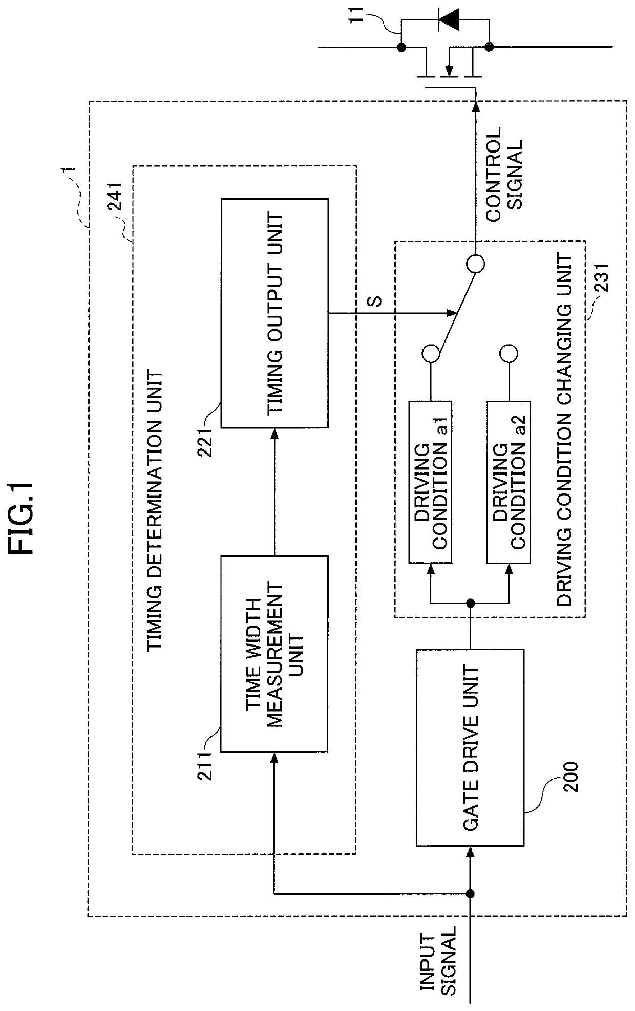
[0015]FIG. 1 is a block diagram illustrating a configuration example of a gate driver 1. The gate driver 1 illustrated in FIG. 1 is a circuit that provides positive or negative voltage to a gate of a switching element 11 to turn on / off the gate of the switching element 11. The gate driver 1 drives the gate of the switching element 11 using an active gate driving technique that adjusts switching speed of the switching element 11 during turn-off of the switching element 11.

[0016]The switching element 11 is a voltage driven semiconductor element having a control electrode (gate), a first main electrode (collector or drain), and a second main electrode (emitter or source). Examples of the switching element 11 include a metal oxide semiconductor field effect transistor (MOSFET), an insulated gate bipolar transistor (IGBT), and the like. FIG. 1 illustrates a case in w...


PUM


Abstract

A gate driver includes: a gate drive unit configured to drive a gate of a switching element in accordance with an input signal that commands to turn on or to turn off the switching element; a timing determination unit configured to measure an on-time width from when the input signal is switched to an on-command to when the input signal is switched to an off-command, and configured to determine, based on the measured on-time width, an intermediate timing that is before switch-off surge voltage of the switching element reaches a peak; and a driving condition changing unit configured to change a gate driving condition of the switching element at the intermediate timing determined by the timing determination unit.

Description

CROSS-REFERENCE TO RELATED APPLICATION[0001]This application is based upon and claims priority to Japanese Patent Application No. 2019-116691, filed on Jun. 24, 2019, the entire contents of which are incorporated herein by reference.BACKGROUND OF THE INVENTION1. Field of the Invention[0002]The present invention relates to a gate driver and a power converter.2. Description of the Related Art[0003]Conventionally, in order to reduce surge voltage and switching losses, an active gate driving technique is known, in which switching speed is changed at an appropriate timing in accordance with drain current or collector current (which may be referred to as main current hereinafter) flowing through a switching element. For example, Patent Document 1 discloses a gate drive circuit that stores a surge period from a timing of a turn-off command to an occurrence timing of voltage surge. At the time of current turn-off, the gate drive circuit determines a timing of changing effective gate resista...

Claims


Application Information

Patent Timeline
IPC IPC(8): H02M1/08H03K17/687H02M3/335H03K17/0412H02M1/00
CPCH03K17/687H03K17/04123H02M1/08H02M3/335H02M2001/0025H02M2001/0006H02M1/32H02M1/0038H02M1/0054H02M3/156H03K17/165H03K17/145H03K2217/0027Y02B70/10H02M1/0006H02M1/0025
Inventor NAGANO, TSUYOSHIMATSUBARA, KUNIO
Owner FUJI ELECTRIC CO LTD
Why Eureka
Try Eureka