
Electric closing element

Active Publication Date: 2020-11-03
AUTO KABEL MANAGEMENTGMBH
View PDF15 Cites 0 Cited by
  • Summary
  • Abstract
  • Description
  • Claims
  • Application Information

AI Technical Summary

Benefits of technology

The invention allows for quick and reliable electrical contact after a motor vehicle accident. The insulation material has strong breaking points, making it easier to break and remove the insulation element when the actuator is triggered.

Problems solved by technology

In addition, relays are complex to manufacture and therefore expensive.
Finally, relays are subject to wear due to ageing.
It is also possible that the switching mechanism of relays is jammed and switching is no longer possible.
A disadvantage of the electrical contactor described here, however, is that due to construction-related tolerances and surface contamination, no reproducible and satisfactory contacts can be made between the closing element and the terminal lugs, so that the reduced transmission cross-sections result in insufficiently fast dissipation of residual capacitance, which also adversely operates only under strong heating.

Method used


Image

  • Electric closing element
  • Electric closing element
  • Electric closing element

Examples


Embodiment Construction

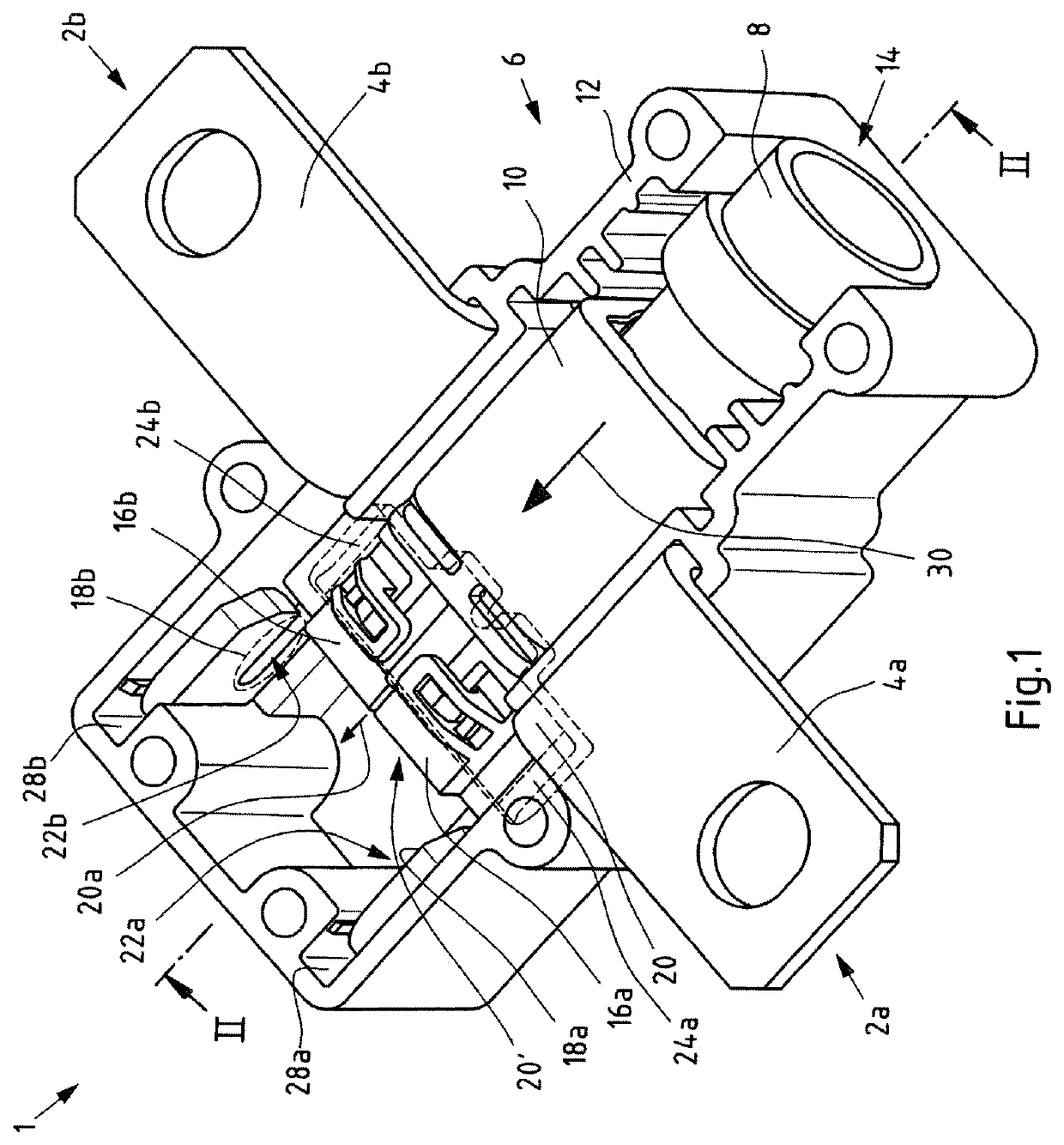
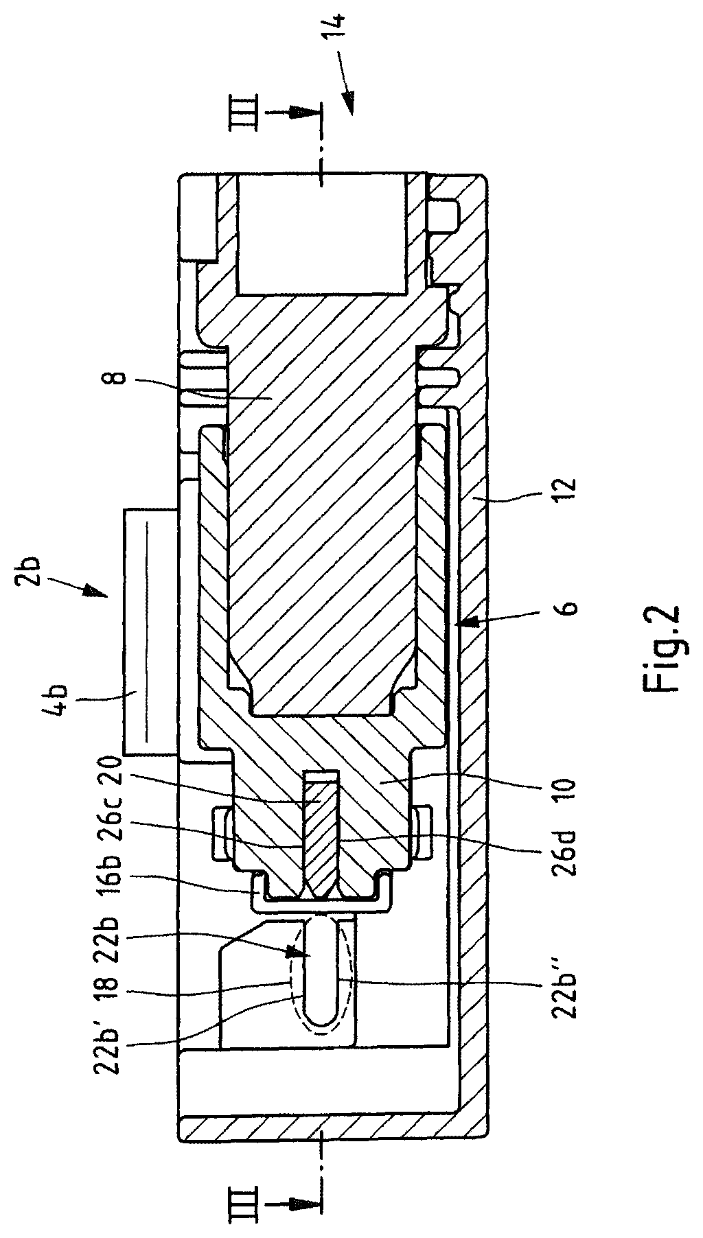
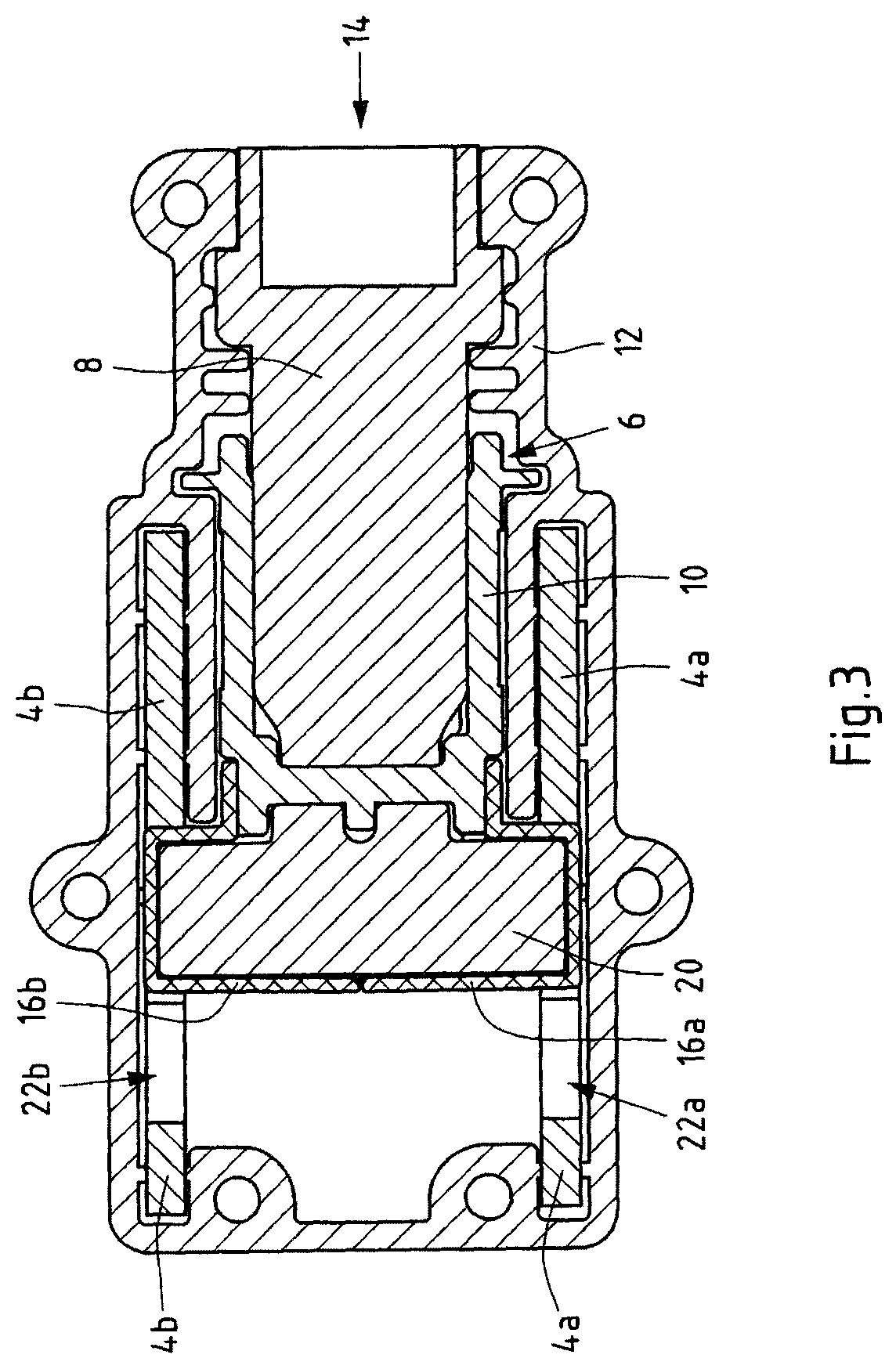
[0067]FIG. 1 shows a view of an electric closer 1 in an open position. An open guide housing 12 can be seen, which forms a guide channel 14 in its interior. An actuator 6 can also be seen, which consists of an actuator unit 8 and a displacement unit 10. The actuator unit 8 can be formed as an drive and convert electrical signals into mechanical motion. However, actuator unit 8 can also be designed as a pyrotechnic actuator unit and, for example, generate a mechanical displacement by igniting a squib by means of a pressure wave. The displacement unit 10 can, for example, be formed as a displacement slide or as a piston which is driven by the actuator unit 8 and performs a translational movement.

[0068]In the case of an embodiment in which a pneumatic impulse is triggered by the actuator unit 8, the guide channel 14 must be well sealed to the outside. In order to prevent an overpressure from occurring during a displacement of the displacement unit 10, which counteracts the movement in ...


PUM


Abstract

An electric closer comprising a first connection lug, a second connection lug electrically insulated from the first connection lug, the first and second connection lugs each having at least one recess in a contact region disposed within a guide housing, an actuator for driving a contact element, the contact element being disposed in a guide housing between the actuator and the contact region of the connection lugs, and by the actuator from an open position, in which the connecting lugs are insulated from one another into a closed position, in which the connecting lugs are electrically connected to one another via the contact element, is displaceable, wherein in the closed position the contact element is accommodated in the recesses of the connecting lugs and wherein the contact element is guided in the displacement direction simultaneously in the respective recesses of the two connecting lugs during the displacement of the two connecting lugs.

Description

CROSS-REFERENCE TO RELATED APPLICATIONS[0001]This application is the national phase entry of international patent application no. PCT / EP2018 / 051570 filed Jan. 23, 2018 and claims the benefit of German patent application No. 10 2017 106 117.7, filed Mar. 22, 2017, the disclosures of which are incorporated herein by reference in their entirety.TECHNICAL FIELD[0002]The object concerns an electric contactor (electrical normal open contact), in particular a high-voltage contactor, as well as a motor vehicle with such a contactor.BACKGROUND ART[0003]Electric contactors are well known. Particularly in automotive applications, electric contactors are often designed as relays. Relays are used to switch a first circuit (switch circuit) by means of a control pulse coming from a second circuit (control circuit), in particular to close it. However, the electrical isolation between the switch circuit and the control circuit is also dependent on the dielectric strength of the air. In addition, rel...

Claims


Application Information

Patent Timeline
IPC IPC(8): H01H1/36H01H39/00H01H1/52H01H9/02
CPCH01H1/365H01H9/02H01H1/52H01H39/004H01H2239/044H01H1/20H01H1/38
Inventor MOSZYNSKI, MARKUSBILLEN, STEFAN
Owner AUTO KABEL MANAGEMENTGMBH
Learn More