Floor panel and method for manufacturing floor panels

a technology for floor panels and manufacturing methods, applied in the field of floor panels, can solve the problems of affecting the monotonous affecting the appearance of the floor panel, etc., and achieves excellent and good scratching and/or wear resistance.

Active Publication Date: 2020-11-10
FLOORING IND LTD
View PDF12 Cites 0 Cited by
  • Summary
  • Abstract
  • Description
  • Claims
  • Application Information

AI Technical Summary

Benefits of technology

[0009]To this aim, the invention, according to a first independent aspect, relates to a floor panel with a substrate and a top layer of laminate, wherein said floor panel, at one or more edges, is provided with a lower edge region in the form of a bevel or other chamfer, with the characteristic that said laminate extends in one piece from the actual upper surface of the substrate over the lower edge region at least up to a point wherein the laminate surface is at a level in a horizontal plane which intersects said substrate, and that the substrate material, at the location of the lower edge region, has approximately the same, the same or a lower density than at the actual upper surface of the substrate material. By means of the continuous laminate surface, an excellent color consistency between the lower edge region and the laminate at the actual upper surface can be obtained, and a water-tight layer is obtained at the lower edge region. As the lower edge region is made relatively deep, a possible deficient adjoining between adjacent floor panels in a floor covering is less irritating. Moreover, the absence of a significant density increase of the substrate material at the location of the lower edge region guarantees the quality of the substrate material at this edge.
[0045]As aforementioned, for the thermally hardening resin of the decor paper preferably a resin on the basis of melamine will be chosen, for example, melamine formaldehyde. Of course, the resin may comprise one or more additives. As additives, flow improvers, such as polyglycol ether, epsilon-caprolactam, ethylene glycol, phthalic acid, phthalic acid ester or butane diol, hardening agents, such as maleic acid, monobutyl phosphoric acid, p-toluene sulfonic acid, citric acid, a blend of one or more of these acids, aluminum sulfate, ammonium chloride or ammonium sulfate or other acids or salts, which in solution offer an acidic pH value, release agents and the like can be applied. A particularly useful additive is a fraction of an acrylic resin, a polyol, such as butane diol or polyurethane diol, a polyolacrylate or another hydroxyfunctional acrylate. Such resin can be at least partially cross-linked or hardened, whereas still a sufficient processability of the decor paper or paper to be printed is maintained. This feature has shown useful to the inventors for performing the method of the invention with an improved repeatability. Working with hydroxyfunctional acrylate, or in other words an acrylate comprising a OH group, has the advantage that OH groups can be brought into the melamine in that the acrylate is soluble in melamine.

Problems solved by technology

Such structure interrupts the monotonous appearance of the panels.
However, the inclined portions of WO'688 are sensitive to water penetration via the inclined surface.
As disclosed in WO'776, adjacent floor panels will not always perfectly adjoin at the height of such lowered edge regions, and at the location of such edge the substrate may become irritatingly visible at the upper surface.
Moreover, the inventors have found that the HDF material compressed at the location of the lower edge regions will experience a quality loss.
This may express itself by a slightly standing upright or upward warping of the laminate edges and possibly the premature loosening of the laminate from the substrate material at the height of these edges, which is detrimental to the water-repellency and the wear resistance of the panels.
Presumably, the connections among the wood fibers will break or be weakened by the extreme pressure exerted thereupon when forming the lower edge regions, and this will lead to the herein above-mentioned negative effects.
It has been found that during the press treatment, possible hard particles, which are provided in the resin, have the tendency to migrate towards higher-situated regions, together with an amount of resin, such that the remaining laminate layer at the location of the lower-situated edge region will be less effective.

Method used


Image

  • Floor panel and method for manufacturing floor panels
  • Floor panel and method for manufacturing floor panels
  • Floor panel and method for manufacturing floor panels

Examples


Embodiment Construction

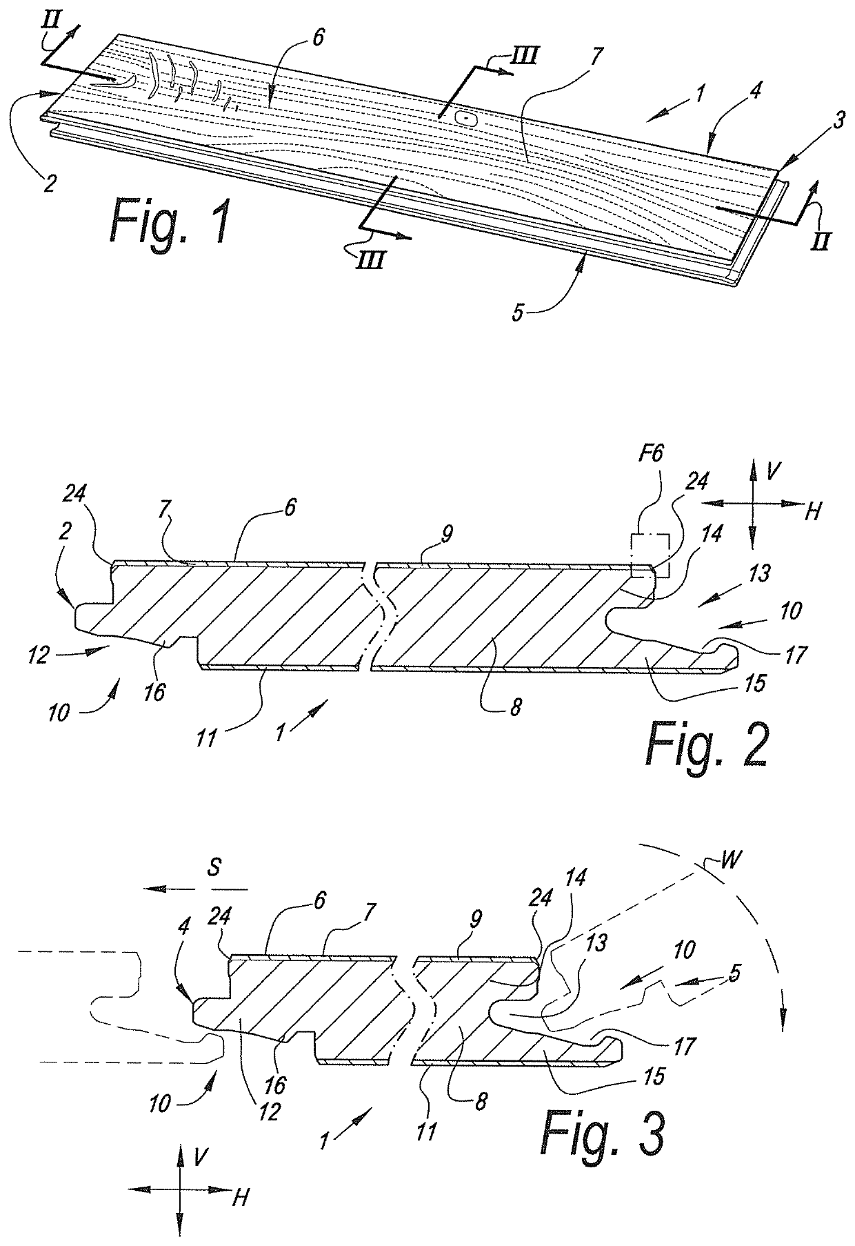
[0068]FIG. 1 represents a decorative panel, more particularly a floor panel 1, in accordance with the invention. The panel 1 is rectangular and oblong and comprises a pair of opposite short edges 2-3 and a pair of opposite long edges 4-5. The decorative top layer 6 is formed by a laminate 7.

[0069]FIG. 2 clearly shows that the decorative panel 1 comprises a substrate 8 on which the laminate 7 is provided, in this case by means of a DPL technique without additional resin or glue layers. To this aim, the laminate 7 is formed on the basis of a thermosetting resin, namely, melamine resin 9. In the example, the substrate material 8 has an average density of more than 800 kilograms per cubic meter. In this case, this concerns an HDF board material having an average density of 900 kilograms per square meter and a surface density or peak density of more than 1000 kilograms per square meter. At the edges 2-3 and 4-5, mechanical coupling means 10 are formed in the substrate material by means o...


PUM

PropertyMeasurementUnit
densityaaaaaaaaaa
angleaaaaaaaaaa
densityaaaaaaaaaa

Abstract

A floor panel with a substrate and a top layer of laminate, which floor panel, at one or more edges, is provided with a lower edge region, wherein the laminate extends in one piece from the actual upper surface of the substrate over the lower edge region at least up to a point, wherein the laminate surface is situated at a level in a horizontal plane which intersects the substrate, and that the substrate material, at the location of the lower edge region, has the same or a lower density than at the actual upper surface of the substrate material. The invention also relates to a method for realizing such floor panels.

Description

BACKGROUND OF THE INVENTION[0001]This invention relates to floor panels, as well as to a method for manufacturing such floor panels.[0002]More particularly, the invention relates to floor panels with a substrate and a top layer of laminate. Such floor panels are well-known as such, for example, from WO 97 / 47834. Herein, this may relate, for example, to floor panels with a substrate which substantially consists of an HDF board with a laminate layer directly pressed thereon, which layer comprises one or more paper sheets soaked in melamine resin, amongst which preferably also a paper sheet with a print in, for example, a wood or stone motif, namely a so-called decor paper.[0003]In view of the fact that a melamine surface as such may impart a monotonous and sometimes plastic-like appearance to the panels, various possibilities are known in the state of the art in order to impart a more attractive appearance to this surface.[0004]From WO 01 / 96689, WO 2006 / 063803, WO 2006 / 066776 and WO 2...

Claims


Application Information

Patent Timeline
Patent Type & Authority Patents(United States)
IPC IPC(8): B32B3/10E04F15/10B32B29/00B32B27/28B32B21/02B32B3/06B44C5/04E04F15/02
CPCB32B29/00B32B27/28B44C5/0476B32B21/02E04F15/02033E04F15/107B32B3/06E04F15/102E04F15/02038E04F2201/0146E04F2201/0153B32B2419/00E04F2201/0552E04F2201/0535
Inventor VANDEVOORDE, CHRISTOF
Owner FLOORING IND LTD
Why Eureka
Try Eureka