Projector type headlamp

a projector type and headlamp technology, applied in the direction of lighting and heating apparatus, instruments, lighting support devices, etc., can solve the problems of troublesome color appearance, unsatisfactory regulations, and large luminous intensity at the positions, so as to increase efficiency and reduce stray lights

Active Publication Date: 2020-11-10
STANLEY ELECTRIC CO LTD +1
View PDF15 Cites 0 Cited by
  • Summary
  • Abstract
  • Description
  • Claims
  • Application Information

AI Technical Summary

Benefits of technology

[0015]In order to assemble the two lenses without a spacer, a wall extending perpendicularly to the lens edge of a lens has to be provided. When T12 / EFL is equal to or greater than 0.1, the thickness of the wall extending perpendicularly to the lens edge becomes so great that the formability of the lens will deteriorate. Further, the distance between the front side of the lens unit and the light source becomes greater, and therefore the size of the headlamp unit becomes greater. Further, the distance between the surface on the light source side of the light-source-side lens and the light source becomes smaller, and therefore the lens will be more easily affected by heat.
[0017]When the above-described condition is satisfied, a sufficiently great value of the center thickness of the light-source-side lens provided with the diffraction grating, can be ensured, and therefore the eccentricity of wall thickness can be reduced to reduce difficulties in forming.
[0023]According to the present embodiment, a diffraction grating is provided only in the area through which the light rays that reach an area around the upper periphery of the light distribution pattern and that might cause the problem of an appearance of colors. Consequently, the efficiency can be increased by reducing the loss due to diffraction, and stray lights can be reduced.

Problems solved by technology

The appearance of colors is troublesome.
However, when a light distribution pattern of the low beam is formed by the projection lens unit provided with a diffraction grating on a surface thereof, rays of the 0-order light of the diffraction grating reach positions above the cut-off line of the light distribution pattern on a virtual screen, and luminous intensity at the positions might be so great that regulations might not be satisfied.

Method used


Image

  • Projector type headlamp
  • Projector type headlamp
  • Projector type headlamp

Examples


Embodiment Construction

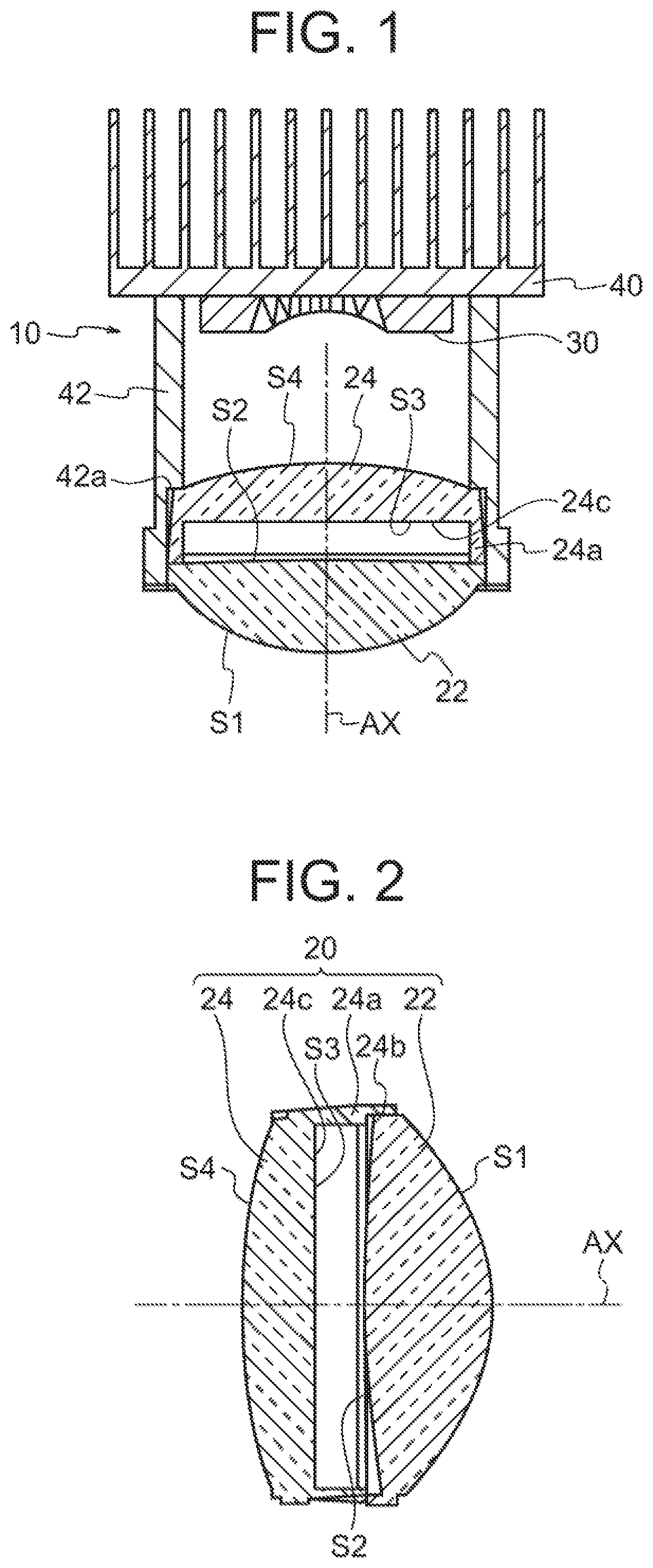
FIG. 1 shows a cross section of a lighting unit 10 of a projector type headlamp according to an embodiment of the present invention. The lighting unit 10 includes a projection lens unit 20 located along an optical axis AX that extends in the longitudinal direction of a vehicle and a light source unit 30 located in the rear of the back focal plane of the projection lens unit 20. FIG. 1 shows a cross section containing the optical axis AX.

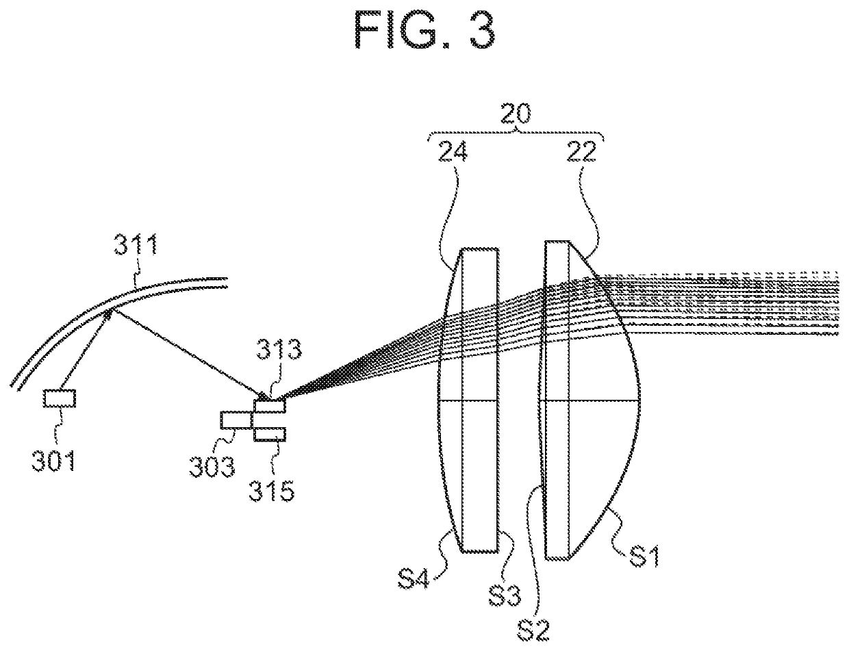
[0040]The projection lens unit 20 is composed of two synthetic resin lenses (plastic lenses), that is, a first synthetic resin lens 22 and a second synthetic resin lens 24 located along the optical axis AX with a certain space between them. The first synthetic resin lens 22 and the second synthetic resin lens 24 are held by a lens barrel 42 that is fixed to a supporting member40 and located along the optical axis AX. Inside the front end (on the opposite side from the light source) of the lens barrel 42, a seat 42a that extends laterally on the insid...


PUM

PropertyMeasurementUnit
areaaaaaaaaaaa
focal lengthaaaaaaaaaa
thicknessaaaaaaaaaa

Abstract

The projector-type headlamp comprises a projection lens unit and a light source unit. A diffraction grating designed to eliminate chromatic aberrations is provided on at least part of a lens surface of the lens unit. When an x axis in the horizontal direction and a y axis in the vertical direction are defined on a plane perpendicular to the optical axis, R1 is the maximum y coordinate on the lens surface, and 0≤A<1, an area of the lens surface in which y<A·R1 comprises a curved surface or a flat surface, at least partially provided with the diffraction grating, and an area of the lens surface in which y≥A·R1 comprises a separate curved surface that has a power greater than the power of the curved surface or flat surface, and is not provided with a diffraction grating.

Description

CROSS REFERENCE TO RELATED APPLICATION[0001]This is a Continuation of International Patent Application No. PCT / JP2017 / 017848 filed May 11, 2017, which designates the U.S. and which claims priority from U.S. Provisional Patent Application No. 62 / 336,802, dated May 16, 2016. The contents of these applications are hereby incorporated by reference.BACKGROUNDTechnical Field[0002]The present invention relates to a projector type headlamp.Background Art[0003]In a projector type headlamp, colors appear around the boundary between light and darkness on the periphery of a light distribution pattern due to chromatic aberrations of the projection lens unit of the projector type headlamp. The appearance of colors is troublesome. In order to reduce these colors that appear, the chromatic aberrations of the projection lens unit has to be compensated. Under the above-described situation, a diffraction grating provided on a surface of the projection lens unit has been proposed in order to reduce the...

Claims


Application Information

Patent Timeline
Patent Type & Authority Patents(United States)
IPC IPC(8): F21V21/00G02B5/18G02B27/00F21S41/40F21S41/275F21V5/04G02B13/00F21S41/255F21S41/00
CPCF21V5/04G02B13/00F21S41/275F21S41/255G02B27/0037F21S41/40F21S41/00G02B5/1814F21S41/143F21S41/663F21S41/151G02B19/0014G02B19/0061G02B19/0052
Inventor KUROSU, HIROAKIKINOSHITA, KAYURIHATADE, KOUEISAKAGAMI, NORIHISA
Owner STANLEY ELECTRIC CO LTD
Why Eureka
Try Eureka