Prepreg and laminate

a technology of laminate and pre-preg, which is applied in the field of pre-preg, can solve the problems of poor connection between the semiconductor element and the printed wiring board of the semiconductor plastic package or between, the limit of responding to the demand for high heat resistance, and the decrease of drillability, so as to achieve high rigidity, low thermal expansion coefficient, and high reliability.

Active Publication Date: 2016-01-19
MITSUBISHI GAS CHEM CO INC
View PDF18 Cites 1 Cited by
  • Summary
  • Abstract
  • Description
  • Claims
  • Application Information

AI Technical Summary

Benefits of technology

[0017]The laminate and metal foil-clad laminate obtained by curing the prepreg according to the invention are high in the rigidity and low in the thermal expansion coefficient. Therefore, the prepreg of the invention is preferred as a material for semiconductor plastic packages which are required to be thin and highly reliable. More specifically, according to the invention, it is possible to provide a printed wiring board for semiconductor plastic packages with improved connection reliability when a semiconductor element is mounted thereon.EMBODIMENTS FOR CARRYING OUT THE INVENTION
[0018]The prepreg of the invention is composed of (A) a glass cloth having specified weight W (g / m2) per 1 m2 of the glass cloth, thickness t (μm) of the glass cloth, end count X (thread / inch) of warp threads per inch and end count Y (thread / inch) of weft threads per inch, and a resin composition comprising (B) a cyanate ester resin, (C) a non-halogen based epoxy resin and (D) an inorganic filler.
[0019]The glass cloth (A) used in the prepreg of the invention is preferably a glass cloth wherein a cross section of each yarn constituting the glass cloth is flattened to make flexion of straightforward yarns small. It is not particularly limited as long as when the weight per 1 m2 of the glass cloth is W (g / m2), the thickness of the glass cloth is t (μm), the end count of warp threads per inch (2.54 cm) (i.e., weaving density of warp threads) is X (thread / inch), and the end count of weft threads per inch (2.54 cm) (i.e., weaving density of weft threads) is Y (thread / inch), the total of X and Y is 150 to 240, t is 17 to 35, the value of W / t is 1.1 to 1.5. Preferably, W / t is 1.1 to 1.4, and also the total of X and Y is preferably 150 to 200, more preferably 150 to 170. W / t has a dimension of g / cm3, and is an apparent density including gap spaces in the weaving structure of the glass cloth. In the glass cloth, when the weight W per unit area is heavy, the thickness becomes thick, while when the thickness t is thin, the weight W per unit area becomes light, so that it is conventionally impossible to manufacture a glass cloth establishing a heavy weight and a thin thickness, that is a glass cloth having a high apparent density. When the value of W / t is less than 1.1, the effect of decreasing the thermal expansion coefficient is small, while when it exceeds 1.5, the formability is unfavorably deteriorated. Also, when t is less than 17 μm, the rigidity of the resulting laminate becomes low, while when t exceeds than 35 μm, it is difficult to manufacture a target thin laminate. Moreover, when the total of X and Y is less than 150, the rigidity of the resulting laminate becomes low and the thermal expansion coefficient becomes high, while when the total of X and Y exceeds 240, it is difficult to manufacture a target thin laminate.
[0020]As the above glass cloth (A), it is preferable to be a woven fabric made from yarns each being a bundle of 75 to 150 glass monofilaments with an average diameter in section of 3.5 to 5.1 μm. When using a glass cloth obtained from yarns each being a bundle of 75 or more glass monofilaments with an average diameter in section of more than 5.1 μm, and having the total of X and Y of not less than 150, the thickness of the prepreg increases, which is not preferable. Preferably, there may be included a glass cloth made from yarns (BC1500) each being a bundle of 100 glass monofilaments with an average diameter in section of 3.5 to 4.7 μm and having the total of X and Y of 150 to 240 and t of 17 to 25 μm, a glass cloth made from yarns (C1200) each being a bundle of 100 glass monofilaments with an average diameter in section of 3.5 to 5.1 μm and having the total of X and Y of 150 to 240 and t of 20 to 28 μm, and so on.
[0021]The weaving type of the glass cloth (A) is not particularly limited, and can utilize well-known ones. Also, as a material of the glass cloth can be used well-known ones used in various types of printed wiring board materials. For example, the material of the glass cloth includes glass fibers such as E-glass, D-glass, S-glass, NE-glass and T-glass, but E-glass can be preferably used in terms of drillability.
[0022]As the cyanate resin (B) used in the resin composition constituting the prepreg of the invention can be typically used any well-known cyanate resins. For example, the cyanate resin (B) includes 1,3-dicyanato benzene, 1,4-dicyanato benzene, 1,3,5-tricyanato benzene, bis(3,5-dimethyl-4-cyanatophenyl)methane, 1,3-dicyanato naphthalene, 1,4-dicyanato naphthalene, 1,6-dicyanato naphthalene, 1,8-dicyanato naphthalene, 2,6-dicyanato naphthalene, 2,7-dicyanato naphthalene, 1,3,6-tricyanato naphthalene, 4,4′-dicyanatobiphenyl, bis(4-cyanatophenyl)methane, 2,2′-bis(4-cyanatophenyl)propane, bis(4-cyanatophenyl)ether, bis(4-cyanatophenyl)thioether, bis(4-cyanatophenyl)sulfone, a phenol novolac type cyanate, and a naphtol aralkyl type cyanate represented by the above general formula (1). In order to enhance flame retardance, the cyanate resin represented by the above general formula (1) can be preferably used. A resin composition including the naphtol aralkyl type cyanate can be preferably used since heat resistance can be maintained by a feature that the resin skeleton is a rigid structure but also the reaction inhibiting factors are reduced to enhance the curing property and the properties such as water absorbency and hygroscopic heat resistance are excellent.

Problems solved by technology

In the technique of setting the epoxy resin with dicyandiamide, however, there is a limitation in responding to the demand for high heat resistance.
However, since the phosphorous compound may have fear of generating a toxic compound such as phosphine or the like upon combustion, it is desired to develop a laminate having flame retardance without using the halogen based compound and phosphorous compound.
Moreover, it is known that upon thinning of the material for the printed wiring board is decreased rigidity of a laminate material for the printed wiring board to cause warpage due to the difference in thermal expansion coefficient in plane direction between a semiconductor element and a printed wiring board for semiconductor plastic package.
By such a warpage may be caused poor connection between the semiconductor element and the printed wiring board for the semiconductor plastic package or between the semiconductor plastic package and the printed wiring board to be mounted thereon.
However, both the use of the high-strength glass cloth and the method of highly filling the filler have a problem of decreasing drillability.

Method used


Image

  • Prepreg and laminate
  • Prepreg and laminate
  • Prepreg and laminate

Examples


synthesis example 1

Synthesis-1 of α-Naphthol Aralkyl Type Cyanate Resin

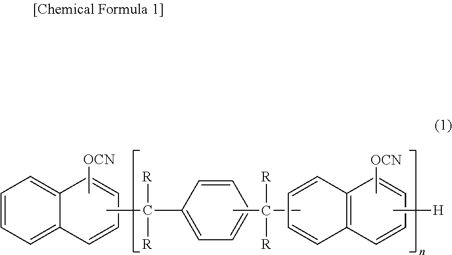
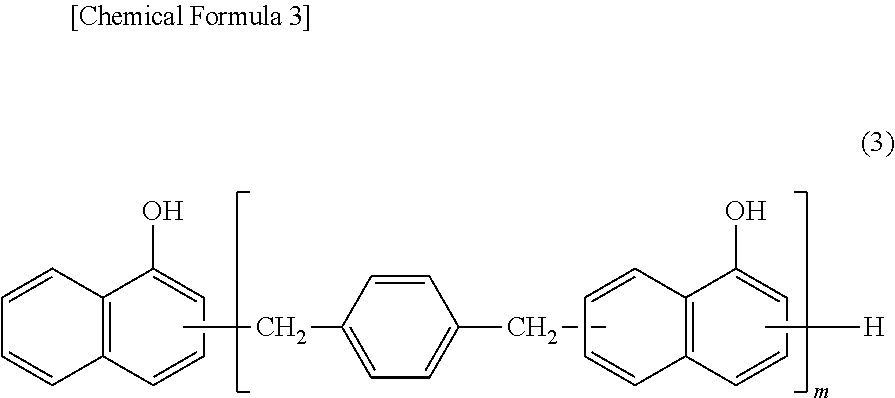
[0036]103 g (OH group 0.47 mole) of α-naphthol aralkyl resin (SN485, OH group equivalent: 219 g / eq., softening point: 86° C., made by Nippon Steel Chemical Co., Ltd.) represented by the following general formula (3):

[0037]

is dissolved in 500 ml of chloroform, and added and mixed with 0.7 mole of triethylamine, which is added dropwise to 300 g of a solution of 0.93 mole of cyanogen chloride in chloroform at −10° C. over 1.5 hours and stirred for 30 minutes, and added dropwise with a mixed solution of 0.1 mole of triethylamine and 30 g of chloroform and stirred for 30 minutes to complete the reaction. The resulting triethylamine hydrochloride is filtered off, and the thus obtained filtrate is washed with 500 ml of 0.1 N hydrochloric acid and then washed with 500 ml of water four times. Next, a chloroform layer is extracted from the chloroform / water mixed solution by separation treatment, and then sodium sulfate is added to the chloro...

synthesis example 2

Synthesis-2 of α-Naphthol Aralkyl Type Cyanate Resin

[0039]An α-naphthol aralkyl type cyanate resin represented by the above general formula (4) is synthesized by the same method as in Synthesis Example 1 except that 102 g (OH group 0.45 mole) of α-naphthol aralkyl resin (SN4105, OH group equivalent: 226 g / eq., softening point: 105° C., made by Nippon Steel Chemical Co., Ltd.) is used in stead of the α-naphthol aralkyl resin (SN485, OH group equivalent: 219 g / eq., softening point: 86° C., made by Nippon Steel Chemical Co., Ltd.) and the amount of cyanogen chloride used is 0.90 mole. In an infrared absorption spectrum is confirmed an absorption of cyanate group in the proximity of 2264 cm−1. Also, the conversion from OH group to OCN group as calculated from 13C-NMR and 1H-NMR is not less than 99%. Furthermore, from differential refractive index detection in GPC, the percentage of compounds with n of 1 to 4 is 75% by weight.

Compounding Example 1

[0040]60 parts by weight of α-naphthol ar...

example 9

Compounding Example 9

[0048]A varnish is obtained in the same manner as in Compounding Example 1 except that the amount of spherical fused silica (SC2050MB, made by Admatechs Co., Ltd.) in Example 1 is changed to 200 parts by weight.

[0049]


PUM

PropertyMeasurementUnit
thicknessaaaaaaaaaa
diameteraaaaaaaaaa
diameteraaaaaaaaaa

Abstract

This invention relates to a prepreg having a low thermal expansion coefficient in plane direction and a high rigidity, and more particularly to a prepreg comprising a glass cloth (A), and a resin composition including a cyanate ester resin (B), a non-halogen based epoxy resin (C) and an inorganic filler (D), wherein the glass cloth (A) is characterized that when the weight per 1 m2 is W (g / m2), the thickness is t (μm), the number of warp threads per inch is X (thread / inch), and the number of weft threads per inch is Y (thread / inch), the total of X and Y is 150 to 240, t is 17 to 35, and the value of W / t as the apparent density is 1.1 to 1.5, and that the volume fraction of the glass cloth (A) in the prepreg is 32% to 42%.

Description

TECHNICAL FIELD[0001]This invention relates to a prepreg for printed wiring boards, a laminate and a metal foil-clad laminate using the prepreg.RELATED ART[0002]The printed wiring boards widely used in electronic devices, communication instruments, personal computers and the like are developed with the advance of high densification and high integration. As a metal foil-clad laminate used in the printed wiring board is required a laminate having excellent properties such as heat resistance, low water absorbency, hygroscopic heat resistance and insulation reliability associated therewith. Heretofore, as a laminate for the printed wiring board has been widely used an FR-4 type laminate obtained by setting an epoxy resin with dicyandiamide. In the technique of setting the epoxy resin with dicyandiamide, however, there is a limitation in responding to the demand for high heat resistance. Also, a cyanate resin is known as a resin for the printed wiring board having an excellent heat resis...

Claims


Application Information

Patent Timeline
Patent Type & Authority Patents(United States)
IPC IPC(8): B32B5/24H05K1/03D03D15/00B32B27/38B32B27/04B32B17/04B32B15/20B32B15/08C08J5/24D03D13/00
CPCB32B15/08B32B15/20B32B17/04B32B27/04B32B27/38C08J5/24D03D13/008D03D15/0011H05K1/0366C08J2363/00D10B2505/02H05K2201/029Y10T442/20B32B27/20B32B27/42H05K1/0353C08J2463/00C08J2361/14B32B2260/021B32B2260/046B32B2264/12B32B2264/102B32B2264/104B32B2264/101B32B2262/101B32B2307/558B32B2307/30B32B2553/00D03D15/513C08J5/244B32B15/14B32B2264/10B32B2307/3065B32B2307/546B32B2307/72B32B2307/732B32B2457/08D03D15/267B32B2305/076C08L63/00H05K1/056
Inventor UENO, MASAYOSHIKATO, YOSHIHIRONOBUKUNI, TAKESHI
Owner MITSUBISHI GAS CHEM CO INC
Why Eureka
Try Eureka