Physical quantity sensor, physical quantity sensor device, electronic apparatus, and vehicle

a technology of physical quantity and sensor device, which is applied in the direction of braking system, process and machine control, instruments, etc., can solve the problems of easy stress caused by insufficient bonding strength, and easy stress caused by the difference in thermal expansion coefficient between the support unit and the connection metal layer, etc., to achieve high reliability

Active Publication Date: 2020-11-10
SEIKO EPSON CORP
View PDF22 Cites 0 Cited by
  • Summary
  • Abstract
  • Description
  • Claims
  • Application Information

AI Technical Summary

Benefits of technology

[0008]An advantage of some aspects of the invention is that it provides a physical quantity sensor, a physical quantity sensor device, an electronic apparatus, and a vehicle capable of reducing deterioration in temperature characteristics while reducing a reduction in a bonding strength of a support.

Problems solved by technology

Therefore, stress caused due to a difference in a coefficient of thermal expansion between the support unit and the connection metal layer easily occurs.
Since the bonding of the support unit and the connection metal layer involves the bonding of silicon and metal, there is also a concern that the bonding strength is not sufficient.
Since the upper surface of the support unit is bonded to the support substrate with the insulation layer interposed therebetween, there is a concern that the bonding stress occurring due to the bonding of the support unit and the support substrate is applied to the support unit.
Therefore, there is a concern that the stability of the bonding of the connection metal layer and the insulation layer of the support unit could be damaged or temperature characteristics could deteriorate.

Method used


Image

  • Physical quantity sensor, physical quantity sensor device, electronic apparatus, and vehicle
  • Physical quantity sensor, physical quantity sensor device, electronic apparatus, and vehicle
  • Physical quantity sensor, physical quantity sensor device, electronic apparatus, and vehicle

Examples


first embodiment

[0046]First, a physical quantity sensor according to a first embodiment of the invention will be described.

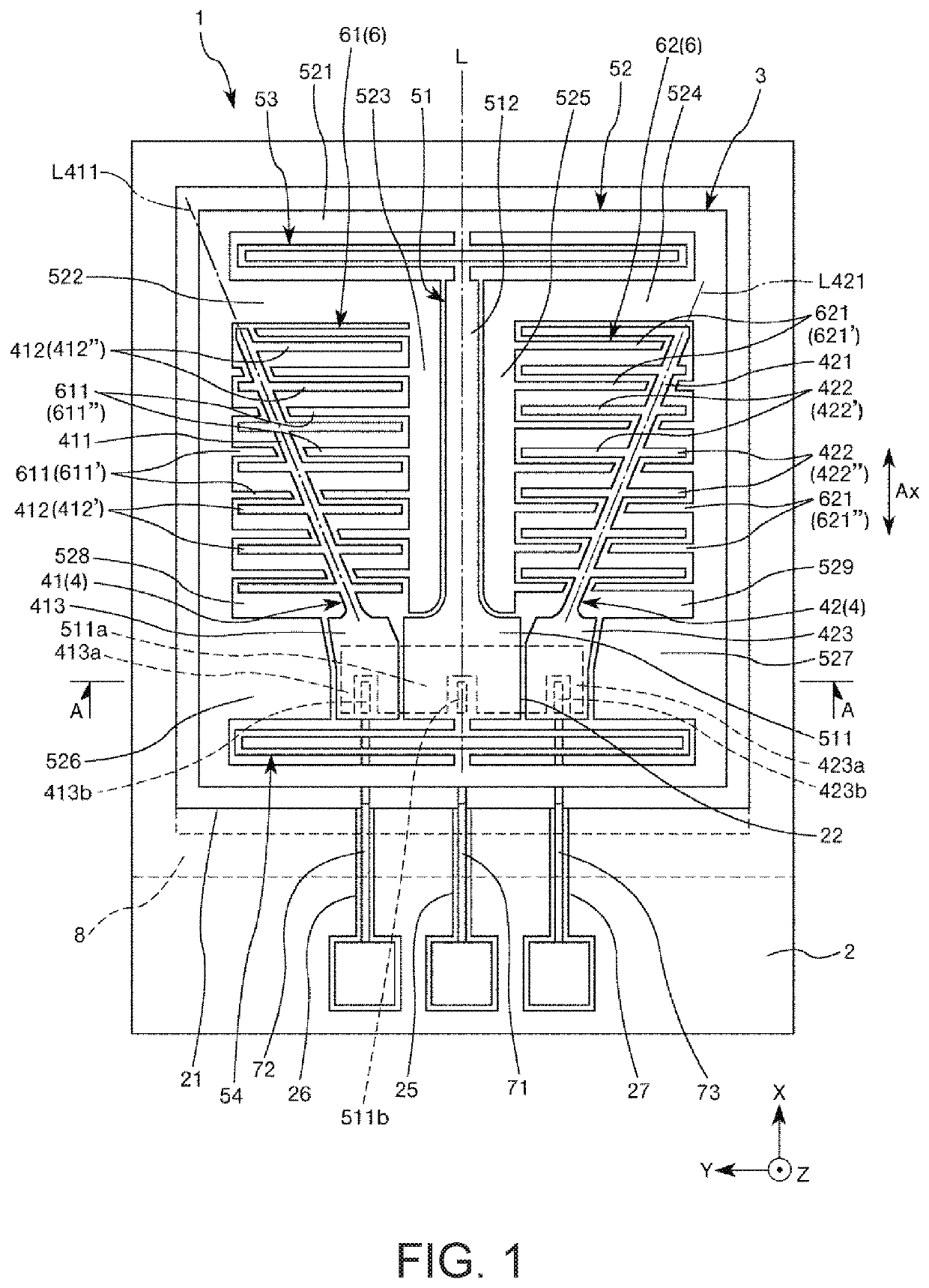
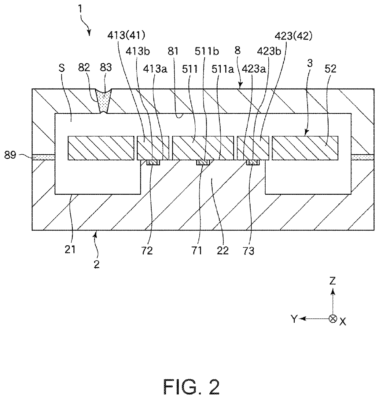
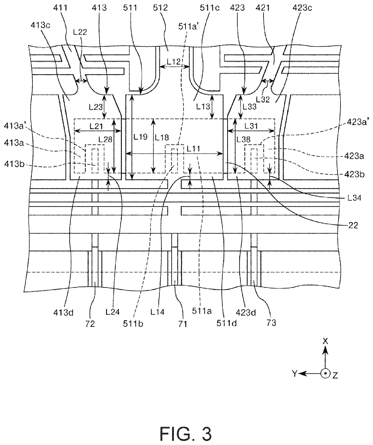
[0047]FIG. 1 is a plan view illustrating a physical quantity sensor according to a first embodiment of the invention. FIG. 2 is a sectional view taken along the line A-A of FIG. 1. FIG. 3 is a partially enlarged plan view illustrating the physical quantity sensor illustrated in FIG. 1. FIGS. 4 and 5 are partially enlarged sectional views illustrating the physical quantity sensor illustrated in FIG. 1. FIG. 6 is a graph illustrating a relation between the length of a first overhang portion and stress applied to a suspension beam. Hereinafter, to facilitate description, the front side of the sheet surface in FIGS. 1 and 3 and the upper side in FIGS. 2, 4, and 5 are referred to a “top” and the rear side of the sheet surface in FIGS. 1 and 3 and the lower side in FIGS. 2, 4, and 5 are referred to as a “bottom”. As illustrated in FIGS. 1 to 5, three axes perpendicular to each other ...

second embodiment

[0116]Next, a physical quantity sensor according to a second embodiment of the invention will be described.

[0117]FIG. 7 is a sectional view illustrating the physical quantity sensor according to the second embodiment of the invention. FIG. 8 is a partially enlarged plan view illustrating the physical quantity sensor illustrated in FIG. 7.

[0118]A physical quantity sensor 1 according to the second embodiment is mainly the same as the physical quantity sensor 1 according to the above-described first embodiment except that the configurations of first bonded surfaces 511a, 413a, and 423a are different.

[0119]In the following description, in the physical quantity sensor 1 according to the second embodiment, differences from the above-described first embodiment will be mainly described and the redundant features will not be described. In FIGS. 7 and 8, the same reference numerals are given to the same elements as those of the above-described first embodiment.

[0120]As illustrated in FIG. 7, ...

third embodiment

[0129]Next, a physical quantity sensor according to a third embodiment of the invention will be described.

[0130]FIG. 9 is a plan view illustrating the physical quantity sensor according to the third embodiment of the invention. In FIG. 9, to facilitate the description, the base, the cover, and the wirings are not illustrated and only the sensor element is illustrated.

[0131]A physical quantity sensor 1 according to the embodiment is mainly the same as the physical quantity sensor 1 according to the above-described first embodiment except that the configuration of the sensor element 3 is different.

[0132]In the following description, in the physical quantity sensor 1 according to the third embodiment, differences from the above-described second embodiment will be mainly described and redundant features will not be described. InFIG. 9, the same reference numerals are given to the same elements as those of the above-described first embodiment.

[0133]As illustrated in FIG. 9, in the embodi...


PUM


Abstract

A physical quantity sensor includes: a base; wiring disposed in the base; a support that includes a first bonded surface bonded to the base and a second bonded surface bonded to the wiring; a suspension beam connected to the support; and an electrode finger supported by the suspension beam. The support is located between the first bonded surface and the suspension beam and includes a first overhang separated from the base.

Description

BACKGROUND1. Technical Field[0001]The present invention relates to a physical quantity sensor, a physical quantity sensor device, an electronic apparatus, and a vehicle.2. Related Art[0002]A known acceleration sensor capable of detecting acceleration is disclosed in International Publication No. 2010 / 032821. The acceleration sensor of International Publication No. 2010 / 032821 includes acceleration sensor elements, and a support substrate and a wiring substrate disposed between the acceleration sensor elements. The acceleration sensor elements include a support unit fixed to the support substrate, a movable electrode unit which is displaceable in a detection axis direction with respect to the support unit, and a fixed electrode unit fixed to the support substrate. With this configuration, the acceleration sensor can detect acceleration based on a change in the electrostatic capacitance formed between the fixed electrode unit and the variable electrode unit.[0003]In the acceleration s...

Claims


Application Information

Patent Timeline
Patent Type & Authority Patents(United States)
IPC IPC(8): G01P15/135B60G17/019G01P15/08G01P15/125B60T8/24G05D1/08
CPCG01P15/125G01P15/135G01P15/08G05D1/0891G05D2201/0213G01P2015/0814B60G2800/01B60G17/01908B60T2230/02G01P2015/0805B60G2400/05B60T8/24G01P15/18
Inventor KIGURE, SHOTA
Owner SEIKO EPSON CORP
Why Eureka
Try Eureka