Layered element made of transparent layers providing directional diffuse reflection

a technology of diffuse reflection and transparent layers, which is applied in the direction of optical elements, synthetic resin layered products, instruments, etc., can solve the problems of not allowing images to be formed on any one of their faces, generating clear reflections, and specular reflections that may dazzle the observer, so as to limit the luminous dispersion of radiation passing and improve the clearness of vision through the layered element

Active Publication Date: 2020-11-10
SAINT GOBAIN VITRAGE SA
View PDF13 Cites 2 Cited by
  • Summary
  • Abstract
  • Description
  • Claims
  • Application Information

AI Technical Summary

Benefits of technology

[0022]By virtue of the invention, the diffuse reflection of the layered element is defined by a plurality of reflection directions that is centered on at least one preferential direction different from the direction of specular reflection. Thus, the or each best angle of observation for the observer, i.e. the angle of observation that allows the observer to observe a projected image with a maximum brightness, is disassociated with the direction of specular reflection. The risk of specular reflection causing dazzle is therefore decreased or even avoided. This directional diffuse reflection, combined with the transparency in transmission of the transparent layered element, allows projected images of good brightness to be obtained. Advantageously, in situations in which the viewing angle is small, it is possible to concentrate the radiation diffusely reflected by the layered element in privileged directions, by selecting a suitable texture for each textured contact surface of the layered element, according to the invention.
[0053]The transparent layered element allows a specular transmission and a diffuse reflection of radiation incident on the layered element from the side of either one of its external layers to be obtained. The central layer of the transparent layered element promotes diffuse reflection, this allowing the direct projection of an image onto either one of the sides of the transparent layered element, and of a transparent glazing incorporating it, the image being formed on the central layer.
[0058]According to one feature, the slope distribution of the texture of each textured contact surface of the layered element, which corresponds to the frequency of each pair of slopes (θx, θy), has, excluding a potential peak centered on O, at least one peak not centered on O and for which the aspect ratio, which is a ratio between the width of the peak along the axis Oθx and the width of the peak along the axis Oθy, is different from 1. The choice of an aspect-ratio value different from 1 makes it possible to obtain a larger angular range of observation in one of the two directions Ox or Oy, this possibly being useful for example when the layered element is integrated into an environment in which the ability to observe is limited in one of the directions.
[0081]As a variant, the deposited layer initially in a viscous, liquid or pasty state may be a layer deposited by a sol-gel process, in particular a sol-gel layer comprising a hybrid organic / inorganic silica-based matrix. Such a sol-gel layer is particularly advantageous because it is possible to adjust with precision the value of its refractive index, so as to make it match as closely as possible that of the textured external layer. According to the invention, the index difference between the two external layers of the transparent layered element corresponds to the absolute value of the difference between the refractive indices at 550 nm of the dielectric materials from which they are made. The smaller the refractive index difference, the clearer vision through the layered element. In particular, excellent vision is obtained with an index difference smaller than or equal to 0.050, preferably smaller than or equal to 0.030 and better still smaller than or equal to 0.015.
[0089]Advantageously, a transparent projection screen or glazing incorporating the layered element comprises at least one antireflection coating at the interface between the air and the material from which the layer forming an external main surface of the glazing is made, said surface being intended to be opposite a projector during the projection of images onto the glazing. The addition of an antireflection coating allows multiple reflections in the interior of the transparent layered element to be decreased and thus the quality of the projected images to be improved.
[0091]The smooth external main surfaces of the transparent layered element and of the transparent projection screen or glazing may be planar or curved. In particular, the transparent layered element may be employed in a curved glazing, for example for buildings or vehicles, in particular motor vehicles. According to one aspect of the invention, the smooth external main surfaces of the transparent layered element may not be parallel to each other, for example in the case of a wedge-shaped layered element intended to be used in a device moreover comprising a head-up display (HUD), in order to avoid ghost images. In other applications, the smooth external main surfaces of the layered element are preferably parallel to each other, this contributing to limiting luminous dispersion of radiation passing through the layered element, and therefore to improving the clearness of vision through the layered element.

Problems solved by technology

It is not envisionable to use standard transparent glazings as projection screens.
Specifically, these glazings do not have diffuse reflection properties, they therefore do not allow images to be formed on any one of their faces and generate clear reflections in the manner of mirrors.
However, any radiation incident on a smooth external surface of the layered element is not entirely transmitted and therefore also gives rise to a specular reflection that may dazzle the observer.
The plurality of directions Rd′ is centered on the direction Rs of specular reflection: the angle of observation αv′ of an observer ideally positioned to observe a projected image is equal to the angle αs of specular reflection, and the observer thus positioned is therefore liable to be discomforted by an undesirable reflection.
However, increasing the angular aperture of the diffuse reflection, for a given projector brightness, amounts to distributing a given amount of light over a large angle, and therefore to decreasing the brightness at each point of the glazing used as screen.
Alternatively, or in addition, the deposition of an antireflection layer is possible but does not allow specular reflection to be completely prevented.

Method used


Image

  • Layered element made of transparent layers providing directional diffuse reflection
  • Layered element made of transparent layers providing directional diffuse reflection
  • Layered element made of transparent layers providing directional diffuse reflection

Examples


Embodiment Construction

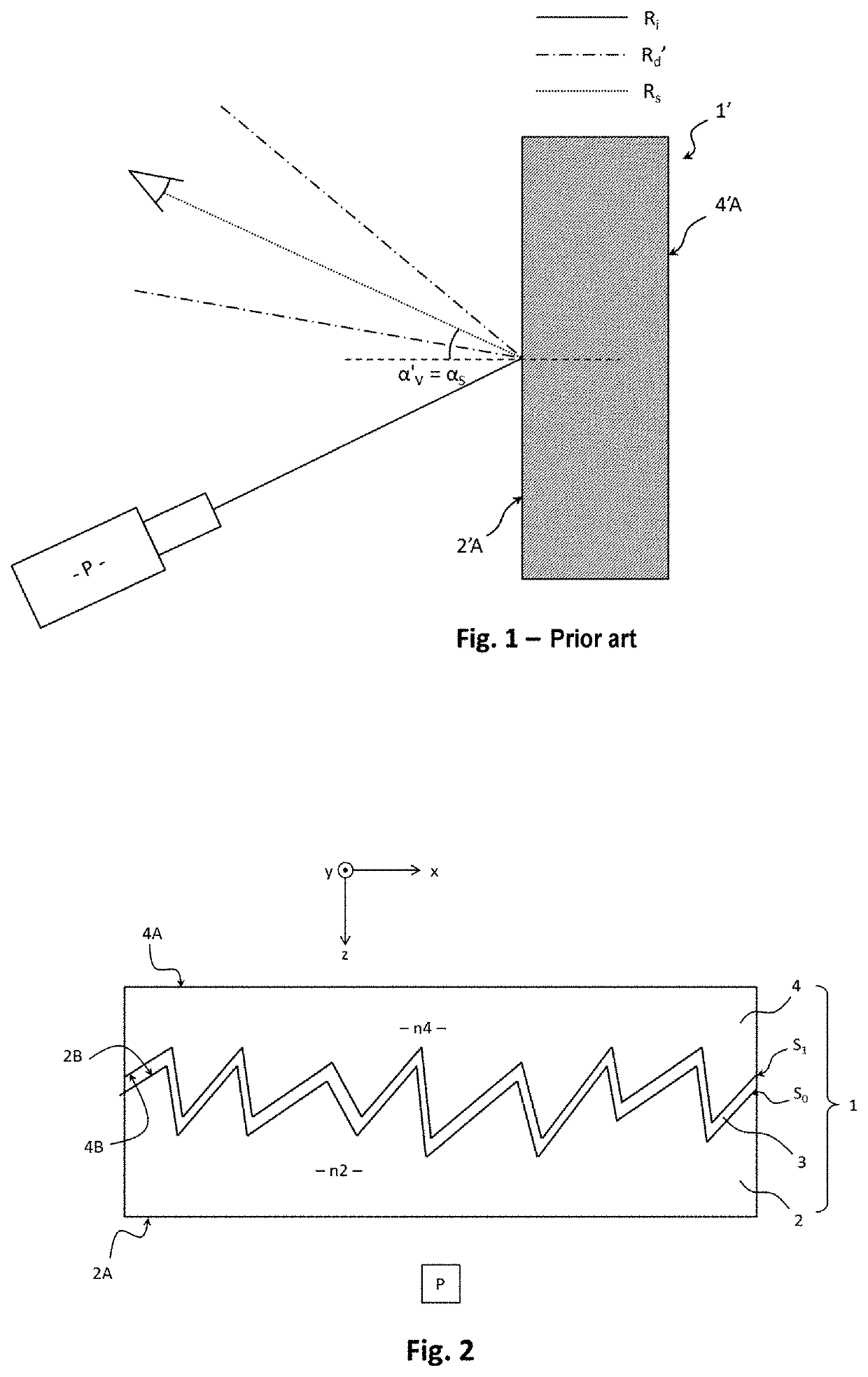
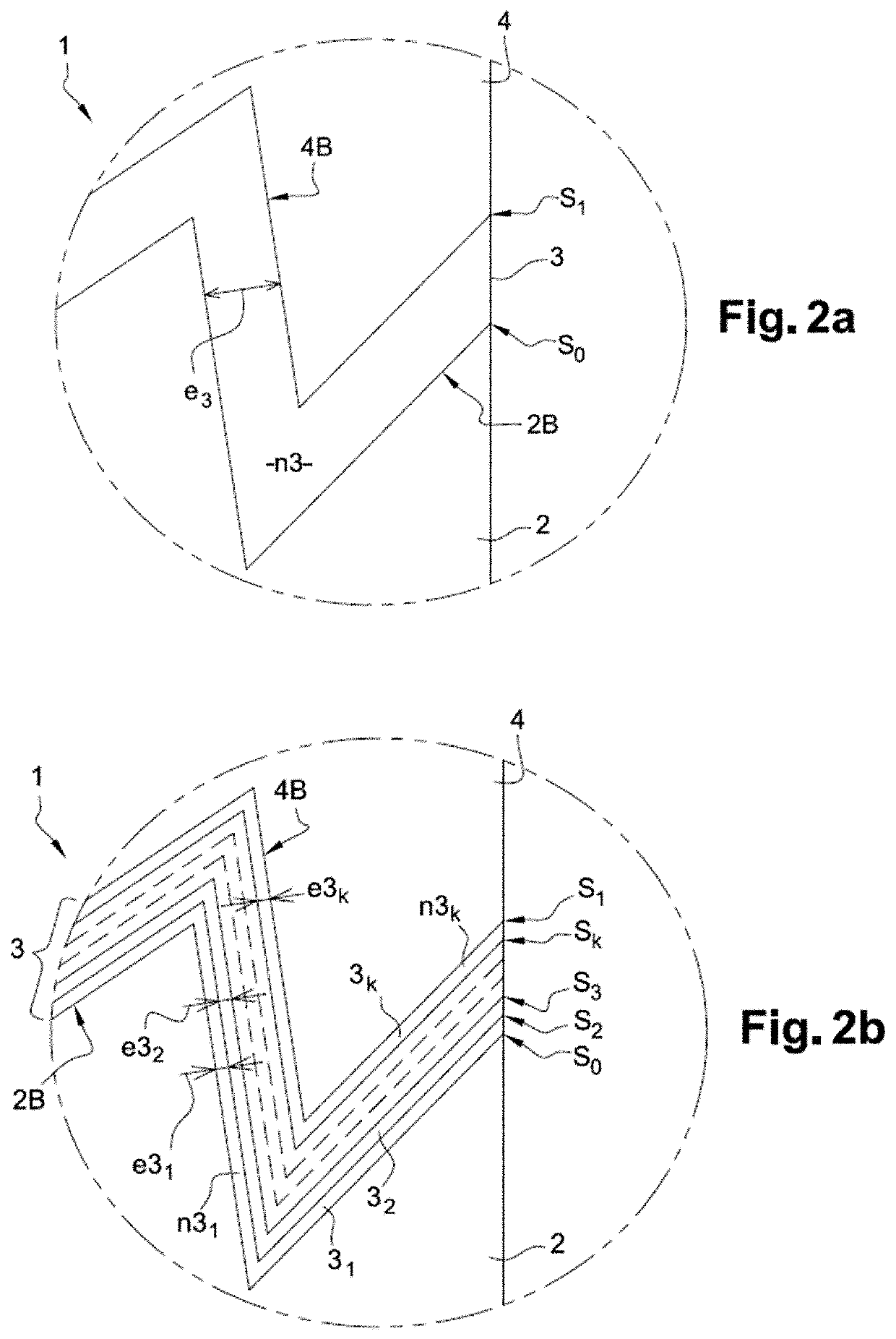
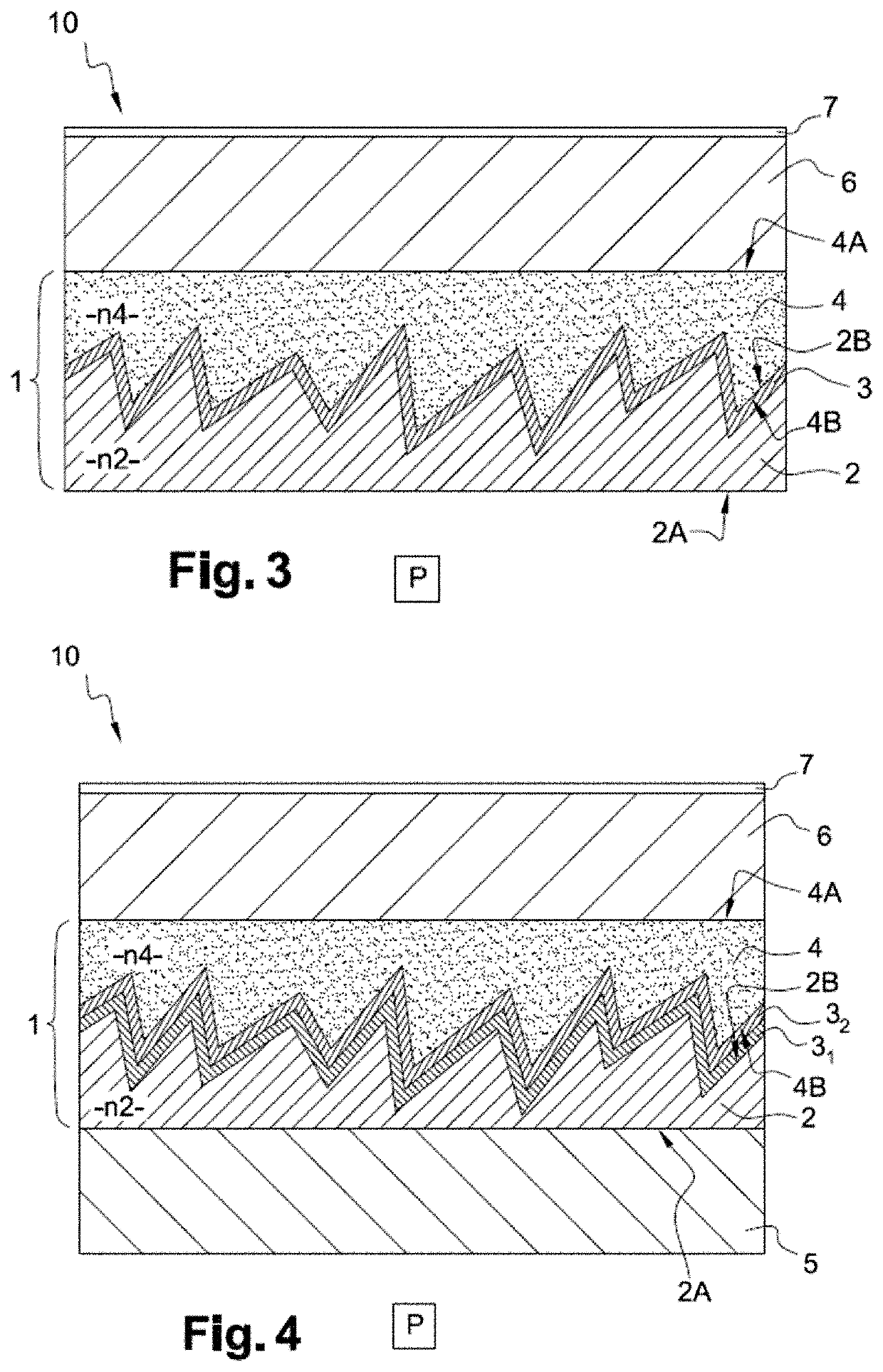
[0110]Unless specified otherwise, a given element appearing in various figures has been referenced with a single reference. For the sake of clarity of the drawings, the relative thicknesses of the various layers have not been rigorously respected in FIGS. 2 to 4. In addition, the possible variation in the thickness of the or each constituent layer of the central layer as a function of the slope of the texture has not been shown in these figures, it being understood that this possible variation in thickness does not affect the parallelism of the textured contact surfaces. Specifically, for each given slope of the texture, the textured contact surfaces are parallel to one another. Moreover, it will be noted that the contact surfaces are shown only schematically in FIGS. 2 to 4, it being understood that their texture respects the slope-distribution criterion of the invention.

[0111]FIG. 1, which schematically shows diffuse and specular reflection of radiation incident on a layered eleme...


PUM

PropertyMeasurementUnit
lengthaaaaaaaaaa
lengthaaaaaaaaaa
lengthaaaaaaaaaa

Abstract

A transparent layered element includes two transparent external layers having substantially the same refractive index and each having a smooth external main surface, and a central layer intermediate between the external layers, the central layer including at least one transparent layer of refractive index different from that of the external layers or a metal layer. All the contact surfaces between two adjacent layers of the layered element, one of the two layers of which is a metal layer, or that are two transparent layers of different refractive indices, being textured and parallel to one another, the diffuse light reflection of the layered element on the side of at least one of the external layers having at least one maximum in a direction different from the direction of specular reflection. In addition, the surface of the layered element is divided into a plurality of pixels of same size.

Description

CROSS-REFERENCE TO RELATED APPLICATIONS[0001]This application is the U.S. National Stage of PCT / FR2018 / 050192, filed Jan. 29, 2018, which in turn claims priority to French patent application number 1750796 filed Jan. 31, 2017. The content of these applications are incorporated herein by reference in their entireties.TECHNICAL FIELD OF THE INVENTION[0002]The technical field of the invention is that of transparent glazings comprising a transparent layered element having diffuse reflection properties. Such transparent glazings may serve as projection screens and may in particular be used in the architectural field or in the transportation field, for example in glazings for airplanes, trains, or motor vehicles (automobiles, trucks, etc.), and in particular in windshields, side windows or glazed roofs.TECHNOLOGICAL BACKGROUND OF THE INVENTION[0003]Known glazings comprise standard transparent glazings, which give rise to specular transmission and to specular reflection of radiation incide...

Claims


Application Information

Patent Timeline
Patent Type & Authority Patents(United States)
IPC IPC(8): G03B21/62G02B5/02G03B21/625G03B21/602G03B21/60G03B21/56G02B5/04G02B1/11
CPCG03B21/56G03B21/62G02B1/11G02B5/0221G03B21/60G02B5/045G03B21/625G03B21/602G02B2207/109B32B17/06B32B17/10036B32B17/10174B32B17/10761B32B7/12B32B27/08B32B9/045B32B27/06B32B2255/10B32B27/36B32B27/308B32B27/365B32B27/40B32B27/281B32B27/34B32B27/322B32B27/304B32B2307/546B32B2605/006B32B2419/00B32B7/023B32B2307/418B32B2307/412B32B2255/24
Inventor SCHIAVONI, MICHELEOZANAM, CECILEGAYOUT, PATRICK
Owner SAINT GOBAIN VITRAGE SA
Why Eureka
Try Eureka