Push-button equipment, pressel therefor and push-button arrangement

a technology of push-button and push-button, which is applied in the direction of mechanical control devices, coupling device connections, elevators, etc., can solve the problems of simple low abrasion during use, and achieve the effect of maintaining the reliability of the holding ability of the button, thin overall structure of the push-button, and reducing the abrasion caused in the button operation

Active Publication Date: 2020-11-10
KONE CORP
View PDF8 Cites 0 Cited by
  • Summary
  • Abstract
  • Description
  • Claims
  • Application Information

AI Technical Summary

Benefits of technology

[0005]A solution is presented, inter alia, by which the overall structure of the push-button is thin. A solution is presented, inter alia, where abrasion caused in button operation can be kept minor. A solution is presented, inter alia, where the holding ability of the locking can be made reliable. A solution is presented, inter alia, where no excessive tilting of the components during installation is necessary which facilitates simplicity of installation from front side of the base, such as a button panel, on which the push-button is to be installed.
[0006]It is brought forward a new push-button equipment comprising a pressel; a mounting collar for being installed on a base, such as a button panel, the mounting collar comprising a seat for receiving the pressel; the pressel comprising a pressing face for receiving a press of a user. The pressel is insertable in the seat of the mounting collar in forward direction orthogonal to the pressing face. The pressel is movable in the seat into a locked position by rotating it in the seat around a rotational axis extending in said direction orthogonal to the pressing face, wherein in said locked position the collar blocks the pressel from moving in backwards direction orthogonal to the pressing face out from the seat. With this solution, one or more of the above mentioned advantages and / or objectives are achieved. This construction makes it possible to install the pressel by push and twist. The overall structure can be thin. Moreover, the amount of abrasion during use can be simply made low due to that locking direction deviates from the installation direction.
[0008]In a preferred embodiment, the collar is arranged to block rotation of the pressel around said rotational axis back from the locked position. This prevents unauthorized removal of the pressel, which for example makes stealing thereof more difficult. It also makes it laborious, or even impossible, to remove the pressel without braking it. Since a new pressel can be mounted without opening the assembly, from maintenance point of view, a worn or a broken pressel can be easily replaced anyways.
[0009]In a preferred embodiment, the pressel comprises a first locking member, and the mounting collar comprises a second locking member, and the pressel inserted in the seat is rotatable in the seat to a locked position around a rotational axis extending in direction orthogonal to the pressing face, such that the first locking member rotates to be positioned in direction of said rotational axis behind the second locking member, whereby in said locked position the second locking member blocks the pressel from moving in backwards direction orthogonal to the pressing face out from the seat. This provides simple locking such that area of surfaces (of the pressel and collar) experiencing abrasion in use, i.e. when the pressel is pressed by the user, can be made only small or even completely eliminated.
[0019]In a preferred embodiment, the returning spring is a bendable tongue helically extending around said rotational axis. Thereby, it can have a thin structure in said direction orthogonal to the pressing face. It is also simple to manufacture.

Problems solved by technology

Moreover, the amount of abrasion during use can be simply made low due to that locking direction deviates from the installation direction.

Method used


Image

  • Push-button equipment, pressel therefor and push-button arrangement
  • Push-button equipment, pressel therefor and push-button arrangement
  • Push-button equipment, pressel therefor and push-button arrangement

Examples


Embodiment Construction

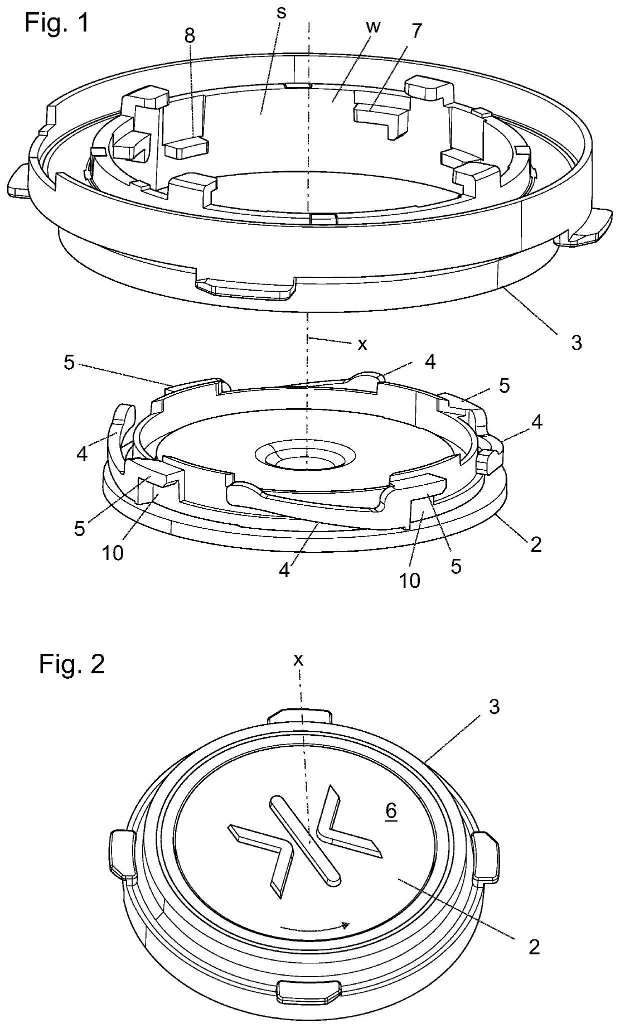
[0048]FIGS. 1 and 2 illustrate a push-button equipment, i.e. a set of push-button components, comprising a pressel 2 and a mounting collar 3 for being installed on a base, such as a button panel, the mounting collar 3 comprising a seat s for receiving the pressel 2. The pressel 2 is mountable on the base via the collar 3. The pressel 2 comprises a pressing face 6 for receiving a press of a user. The pressel 2 is insertable in the seat s of the mounting collar 3 in forward direction orthogonal to the pressing face 6. The pressel 2, after being inserted in the mounting collar 3, is movable in the seat s into a locked position by rotating it in the seat s around a rotational axis x extending in said direction orthogonal to the pressing face 6, wherein in said locked position the collar blocks the pressel 2 from moving in backwards direction orthogonal to the pressing face 6 out from the seat. The pressing face 6 of the pressel 2 is visible in FIG. 2. The reference number x marks also t...


PUM


Abstract

A push-button equipment includes a pressel; a mounting collar for being installed on a base, such as a button panel, the mounting collar including a seat for receiving the pressel; the pressel including a pressing face for receiving a press of a user and being insertable in the seat of the mounting collar in a forward direction orthogonal to the pressing face. The pressel is movable in the seat into a locked position by rotating it in the seat around a rotational axis extending in said direction orthogonal to the pressing face. In said locked position the collar blocks the pressel from moving in backwards direction orthogonal to the pressing face out from the seat. A pressel for the push-button equipment and a push-button arrangement of an elevator are also disclosed.

Description

FIELD OF THE INVENTION[0001]The invention relates to push-buttons, and particularly to push-buttons of an elevator. The elevator is an elevator for transporting passengers and / or goods.BACKGROUND OF THE INVENTION[0002]Conventional push-buttons often comprise a pressel comprising a pressing face for receiving a press of a user, as well as a collar comprising a seat for receiving the pressel.[0003]There are known push-buttons where installation of the pressel is possible by inserting the pressel in the seat of the mounting collar in forward direction orthogonal to the pressing face for receiving a press of a user. With this kind of front-mounted pressels the equipment usually comprises a return spring mechanism and pressel locking mechanism, which are separate from each other. In prior art, with front-mounted pressels, the locking is done by push of the pressel in direction orthogonal to the pressing face until a fixing clip snaps over a counterpart abutment, wherein the direction of ...

Claims


Application Information

Patent Timeline
Patent Type & Authority Patents(United States)
IPC IPC(8): G05G1/02H01H13/7057H01R13/627H01R13/506H01H13/705H01H13/14F16B21/04B66B1/52
CPCH01H13/705H01H13/14H01R13/6277H01R13/506H01H13/7057G05G1/02G05G2505/00B66B1/52F16B21/04B66B1/46B66B1/462H01H13/02H01H13/26H01H13/83
Inventor MAKELA, KLAUSHAUTAMAKI, MIKA
Owner KONE CORP
Why Eureka
Try Eureka