Display prop splicing device

a splicing device and display technology, applied in the field of display, can solve the problems of ineffectively meeting the requirements of conveniently and flexibly mounting a plurality of luminous bodies, and inconvenient splicing, and achieve the effects of improving working efficiency, convenient and flexibly splicing, and improving connection stability between adjacent display bodies

Active Publication Date: 2020-11-10
SHENZHEN FOG LIGHTING CO LTD
View PDF12 Cites 1 Cited by
  • Summary
  • Abstract
  • Description
  • Claims
  • Application Information

AI Technical Summary

Benefits of technology

[0003]The objective of the invention is to provide a display prop splicing device that is simple in structure and capable of conveniently and flexibly splicing a plurality of display bodies.
[0013]The invention has the following beneficial effects: the display prop splicing device provided by the invention includes the display bodies, the luminous bodies and the connecting bodies, wherein the luminous bodies are erected on and electrically connected with the display bodies; the connecting bodies are used for fast electrical connection between the adjacent display bodies; the first mounting site and the second mounting site are respectively formed at the two ends of each connecting body; the third mounting site and the fourth mounting site are respectively formed at the two ends of each display body; the first mounting sites are cooperated with the third mounting sites, and the second mounting sites are cooperated with the fourth mounting sites; when two of the display bodies are connected with each other, the third mounting site of one display body is cooperated with the fourth mounting site of the other display body; the first magnet and the second magnet which are attracted to each other are arranged in each first mounting site and each third mounting site, as well as in each second mounting site and each fourth mounting site; the conductive poles used for the electrical connection between the adjacent display bodies are embedded into the outer edges of each first magnet and each second magnet; and at least one display body is electrically connected with the external electrical control device through the power line. By adopting the display device based on the above structural design, a plurality of display bodies can be conveniently and flexibly spliced through the first mounting sites, the second mounting sites, the third mounting sites and the fourth mounting sites, so that the working efficiency is effectively improved, and the connection stability between the adjacent display bodies is improved.

Problems solved by technology

However, in such implementation, due to the lack of a necessary splicing structure, disassembly and the assembly are inconvenient, the connection stability is poor, and the requirements for conveniently and flexibly mounting a plurality of luminous bodies cannot be effectively met.

Method used


Image

  • Display prop splicing device
  • Display prop splicing device
  • Display prop splicing device

Examples


Embodiment Construction

[0019]The technical scheme of the invention is further explained as follows in combination with the drawings and specific implementations.

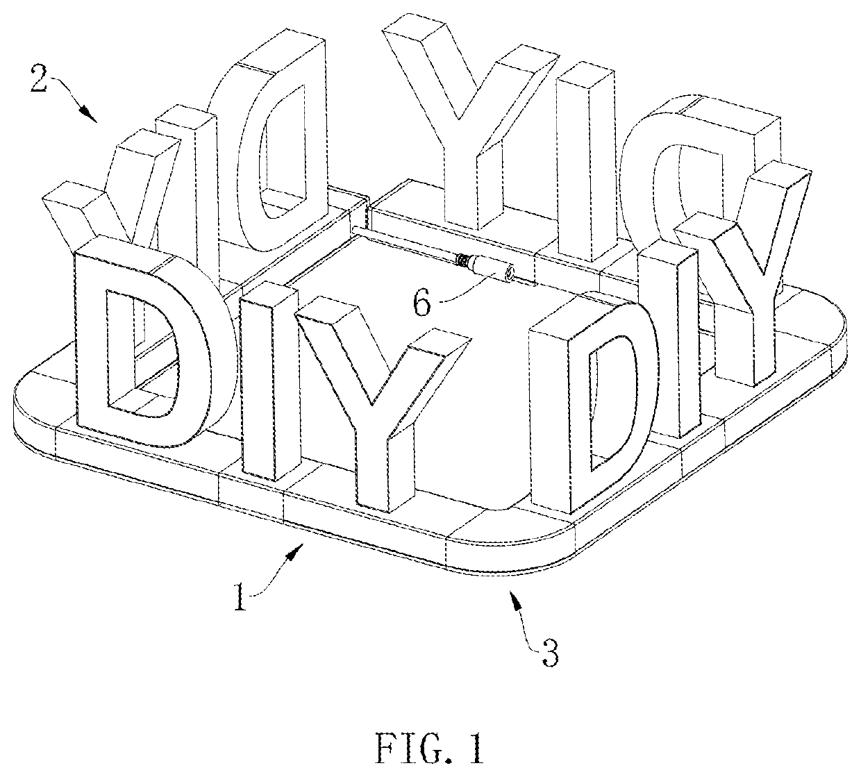
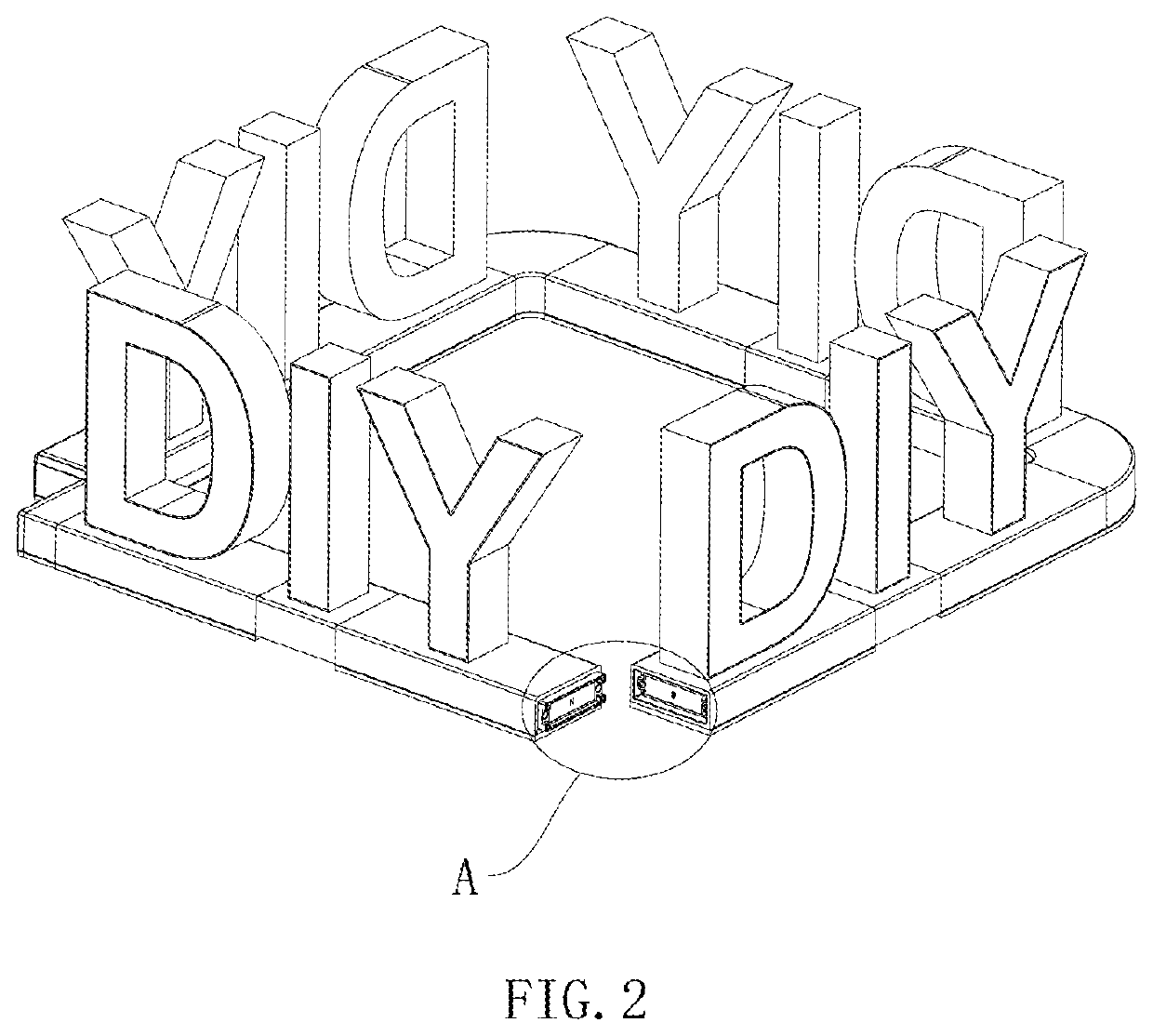
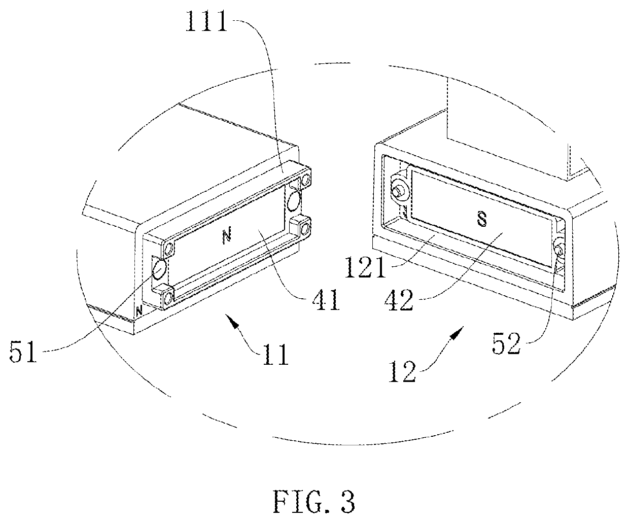
[0020]As shown in FIG. 1 to FIG. 5, this embodiment is provided with a display prop splicing device including display bodies 1, luminous bodies 2, and connecting bodies 3, wherein the luminous bodies 2 are erected on and electrically connected with the display bodies 1; the connecting bodies 3 are used for fast electrical connection between the adjacent display bodies 1; a first mounting site 31 and a second mounting site 32 are respectively formed at two ends of each connecting body 3; a third mounting site 11 and a fourth mounting site 12 are respectively formed at two ends of each display body 1; the first mounting sites 31 are cooperated with the third mounting sites 11, and the second mounting sites 32 are cooperated with the fourth mounting sites 12; when two of the display bodies 1 are connected with each other, the third mounting site 11 o...


PUM


Abstract

A display prop splicing device includes display bodies, luminous bodies, and connecting bodies. A first mounting site and a second mounting site are respectively formed at two ends of each connecting body. A third mounting site and a fourth mounting site are respectively formed at two ends of each display body. A first magnet and a second magnet which are attracted to each other are arranged in each first mounting site and each third mounting site, as well as in each second mounting site and each fourth mounting site. Conductive poles used for electrical connection between the adjacent display bodies are embedded into the outer edges of each first magnet and each second magnet. At least one display body is electrically connected with an external electrical control device through a power line. Multiple display bodies are conveniently and flexibly spliced through the first, second, third and fourth mounting sites.

Description

BACKGROUND OF THE INVENTION1. Fields of the Invention[0001]The invention relates to the technical field of display, in particular to a display prop splicing device.2. Descriptions of Related Art[0002]In the prior art, an advertising word is mostly formed by a base and a luminous body erected on the base. When a plurality of luminous bodies are mounted, the design requirements of the luminous bodies can generally be met by means of the extension of bases or electrical connection of the bases through wires. However, in such implementation, due to the lack of a necessary splicing structure, disassembly and the assembly are inconvenient, the connection stability is poor, and the requirements for conveniently and flexibly mounting a plurality of luminous bodies cannot be effectively met.SUMMARY OF THE INVENTION[0003]The objective of the invention is to provide a display prop splicing device that is simple in structure and capable of conveniently and flexibly splicing a plurality of displ...

Claims


Application Information

Patent Timeline
Patent Type & Authority Patents(United States)
IPC IPC(8): G09F13/00F21V23/06G09F13/22F21V23/00F21V3/00H01R13/62G09F13/04F21Y115/10
CPCF21V23/06G09F13/0404G09F13/22G09F13/0413F21V23/001H01R13/6205F21V3/00G09F2013/0418F21Y2115/10G09F2013/222H01R25/162G09F13/0418G09F13/0409G09F13/04
Inventor DENG, QINGPING
Owner SHENZHEN FOG LIGHTING CO LTD
Why Eureka
Try Eureka