Reflector for vehicles

a technology for reflectors and vehicles, applied in the field of reflectors, can solve the problems of optical interference with the light distribution for a further light function disposed behind

Active Publication Date: 2020-11-17
HELLA KG HUECK & CO
View PDF21 Cites 0 Cited by
  • Summary
  • Abstract
  • Description
  • Claims
  • Application Information

AI Technical Summary

Benefits of technology

[0006]It is therefore an object of the present invention to refine a reflector further in such a way that predetermined reflection values are effectively fulfilled, whereby the reflector is dimensioned smaller in particular and, moreover, has an inconspicuous appearance and can be transilluminated without being disturbed by a further light function positioned behind it.
[0010]According to an embodiment of the invention, the lens to which the hologram element is applied is a cover plate that seals a lamp housing. Because of the very small optical structures of the hologram element, it is suitable for transillumination without photometric losses or effects.
[0011]According to an embodiment of the invention, the hologram element can be attached only at its lateral sides to a holder frame. Because the hologram element in this case is not placed flat on a support, material and weight can be saved as a result.
[0012]According to an embodiment of the invention, the hologram element can have a self-adhesive surface on one of its flat sides, so that the hologram element can be applied anywhere to provide the reflection function. In a vehicle, it can be applied to the cover plate of a fully assembled lamp housing or to a body surface or to a bumper surface. Apart from the vehicle, the hologram element can be placed on stationary objects such as, for example, signs, marking devices, driveways, barriers, delineator posts, in the area of underground garages, etc. This results in a space-saving reflection function for protecting or marking objects.
[0014]According to an embodiment of the invention, the multipart hologram element can have a number of hologram element segments that are perpendicular or at an angle to one another. A reflector function in a number of different directions is assured in this way. For example, a hologram element, placed on a side facing a side of the vehicle, can extend in the direction of travel of the vehicle so as to form a side marking reflector.
[0015]According to an embodiment of the invention, the hologram element has such light information that only spectral light fractions predetermined for the reflection function are reflected. In this way, the hologram element has a filter function which makes it possible that white light is reflected, for example, in a red or orange light color. An additionally colored lens, as is necessary in the case of conventional reflector optics, is not necessary for this purpose.

Problems solved by technology

Conventional reflectors, however, have the disadvantages that a reflective surface must be relatively large so as to achieve a required reflection values, that the reflector optics are visible very conspicuously, and that the reflector optics disrupt the light distribution for a further light function disposed behind it.

Method used


Image

  • Reflector for vehicles
  • Reflector for vehicles
  • Reflector for vehicles

Examples


Embodiment Construction

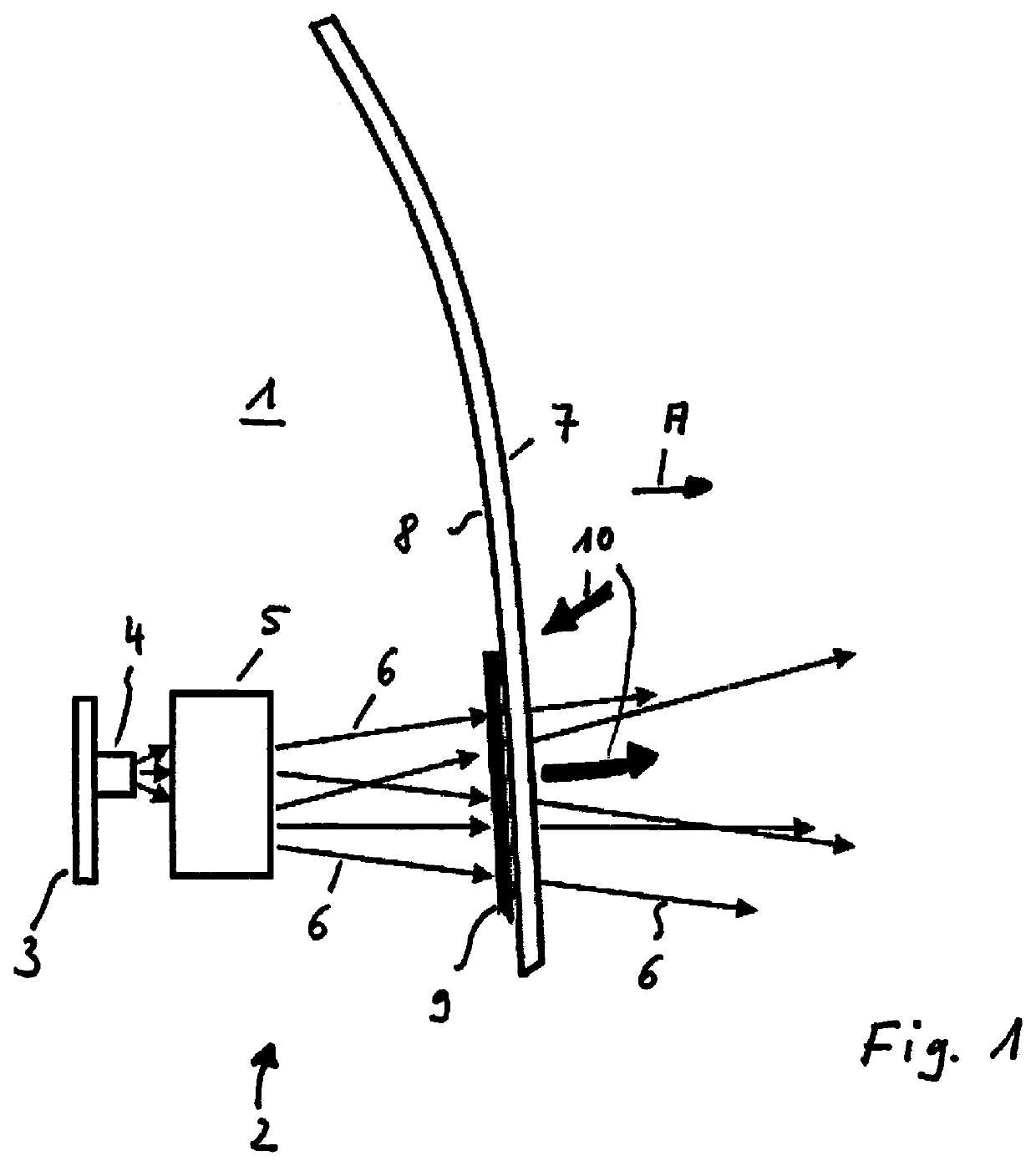
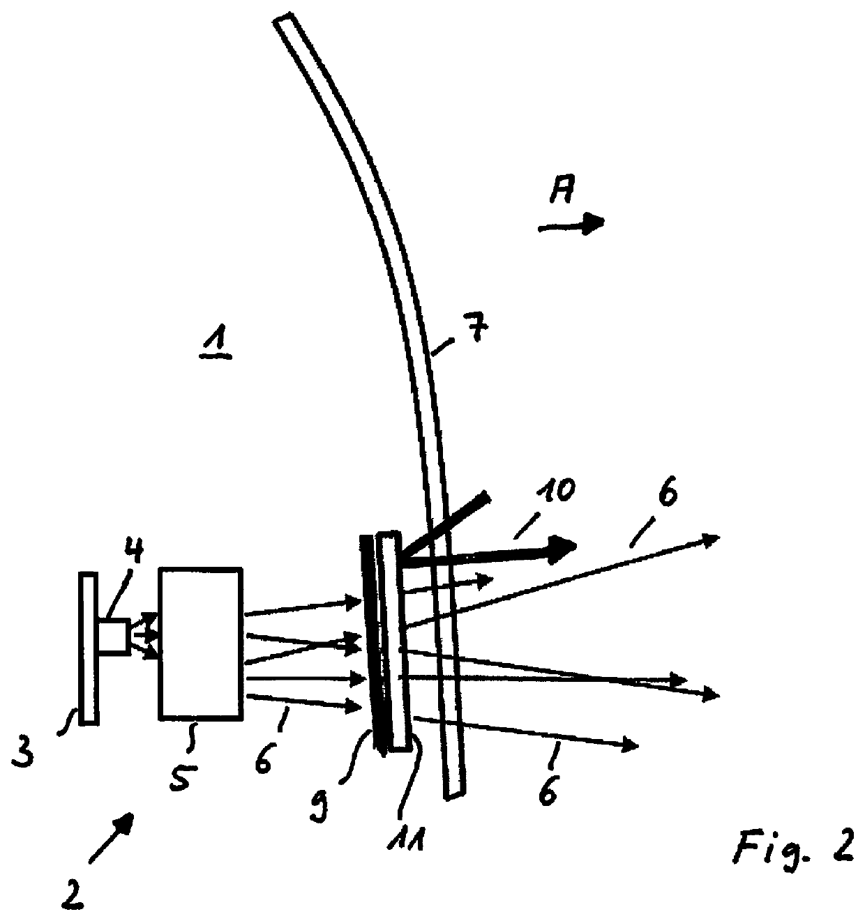
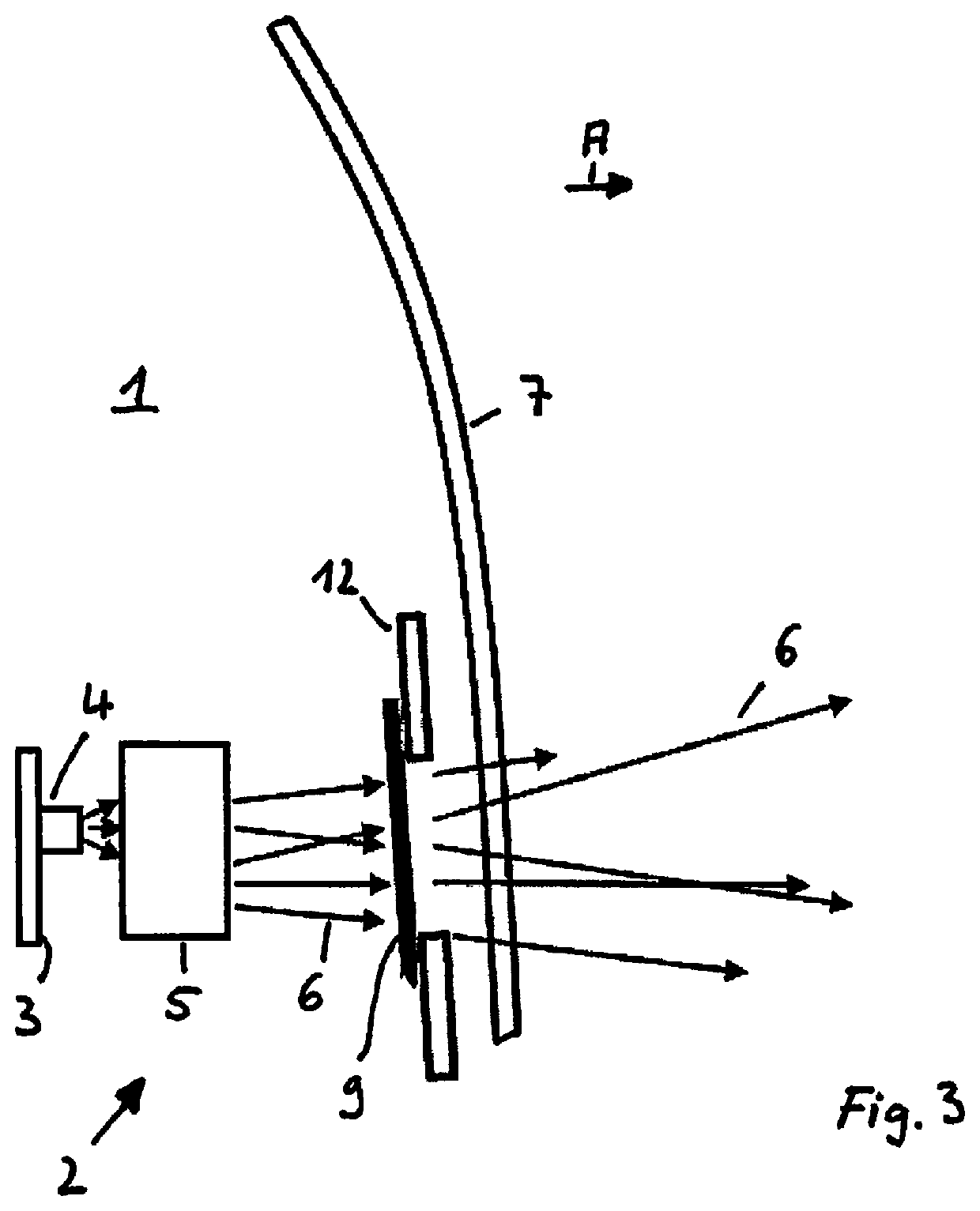
[0027]A reflector of the invention can be disposed in a lamp housing 1 of a vehicle, which can be made, for example, as a rear light. A lamp unit 2 for producing a predetermined light distribution, for example, a tail light or braking light or turning light function is illustrated schematically in FIG. 1. Lamp unit 2 has a light source 4, which is disposed on a printed circuit board 3 and is formed, for example, as an LED light source. An optical unit 5 having one or more lenses or a reflector is disposed in front of light source 4 in a light emission direction (A). Light 6 emitted by light source 4 is formed or reflected according to a predetermined light distribution by means of optical unit 5. A cover plate 7, which seals lamp housing 1, is provided in front of optical unit 5 in light emission direction A. Cover plate 7 can be made crystal clear, for example. A reflective surface 9, which has a hologram element as an optical element for reflecting light incident on the optical el...


PUM

PropertyMeasurementUnit
angleaaaaaaaaaa
reflectionaaaaaaaaaa
grating constantaaaaaaaaaa

Abstract

A reflector for vehicles includes a reflective surface that contains an optical element to reflect light incident on the optical element according to specific reflection characteristics. The reflective surface is designed as a hologram element which has a grating structure in such a way that light incident on the hologram element is reflected according to the specific reflection characteristics.

Description

[0001]This nonprovisional application is a continuation of International Application No. PCT / EP2015 / 078801, which was filed on Dec. 7, 2015, and which claims priority to German Patent Application No. 10 2014 118 308.8, which was filed in Germany on Dec. 10, 2014, and which are both herein incorporated by reference.BACKGROUND OF THE INVENTIONField of the Invention[0002]The invention relates to a reflector for vehicles or other reflecting components and elements, for example, signs or marker devices, comprising a reflective surface that contains an optical element for reflecting light incident on said optical element according to reflection characteristics.Description of the Background Art[0003]EP 2 492 579 A2, which corresponds to U.S. Pat. No. 8,702,258, discloses an illumination device for vehicles for producing a predetermined light distribution according to a projection principle. This projection headlight comprises a light source, a lens, a cover device, and a hologram element, ...

Claims


Application Information

Patent Timeline
Patent Type & Authority Patents(United States)
IPC IPC(8): G02B5/12G03H1/02G02B5/20F21S43/31F21S43/40F21S43/20B60Q1/30G03H1/22F21S43/00G02B5/32
CPCG02B5/203F21S43/00F21S43/315B60Q1/30G02B5/32G02B5/12F21S43/40G03H1/0248F21S43/26G03H2001/2231G03H1/2202
Inventor HOHMANN, CARSTENMUEGGE, MARTIN
Owner HELLA KG HUECK & CO
Why Eureka
Try Eureka