

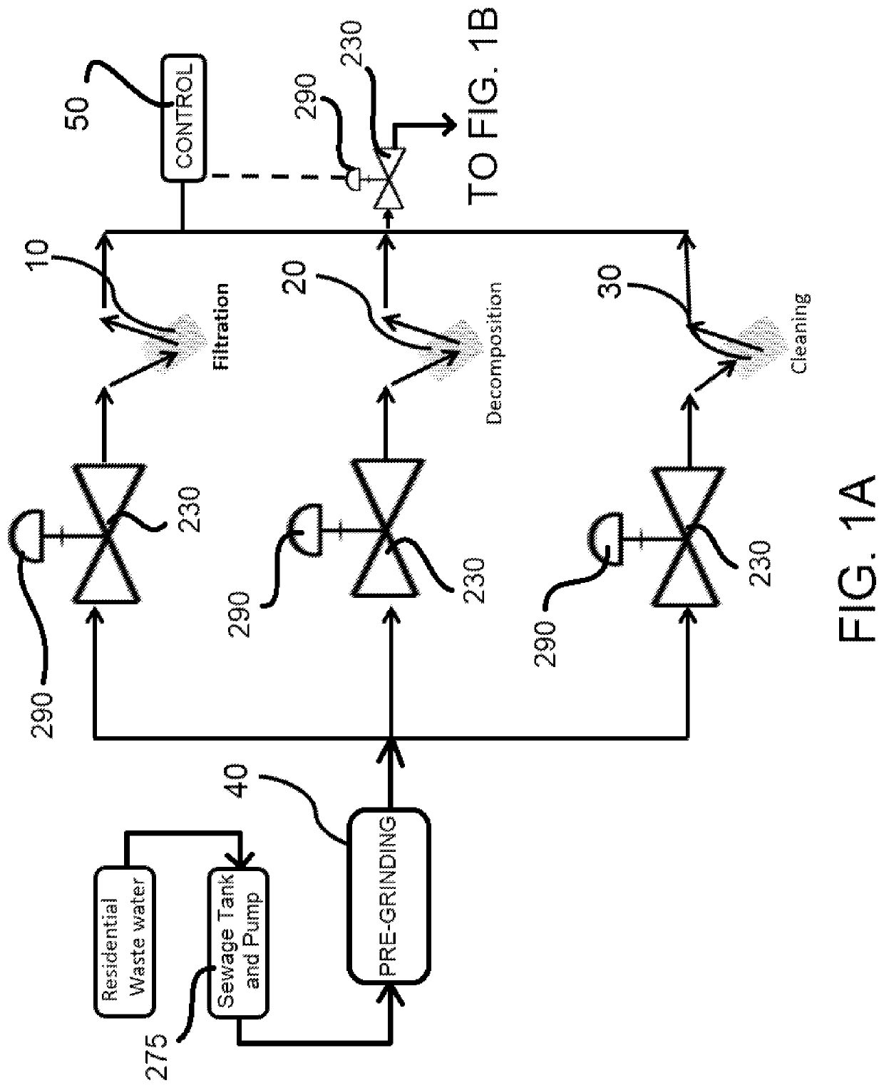
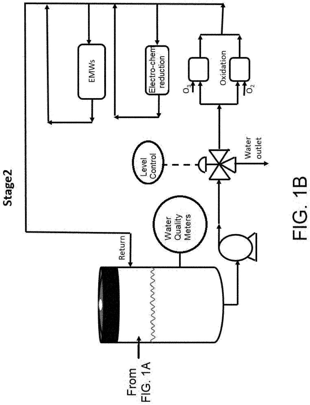
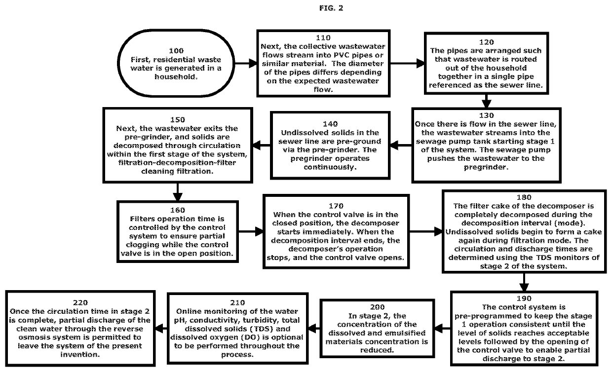
Continuous, approximately real-time residential wastewater treatment system and apparatus
a wastewater treatment system and a technology of residential wastewater, applied in the field of new waste treatment system, can solve the problems of slow water diffusion to the near soil, high variability of waste water composition which the treatment operation must control, and unpleasant smell in the backyard or neighborhood, and achieves non-toxic vapor and nearly drinking water quality output, minimal operational and maintenance costs, and low footprint size
- Summary
- Abstract
- Description
- Claims
- Application Information
AI Technical Summary
Benefits of technology
Problems solved by technology
Method used
Image

Examples
Embodiment Construction
[0019]The present specification discloses one or more embodiments that incorporate the features of the invention. The disclosed embodiment(s) merely exemplify the invention. The scope of the invention is not limited to the disclosed embodiment(s). The invention is defined by the claims appended hereto.
[0020]References in the specification to “one embodiment,”“an embodiment,”“an example embodiment,” etc., indicate that the embodiment described may include a particular feature, structure, or characteristic, but every embodiment may not necessarily include the particular feature, structure or characteristic. Moreover, such phrases are not necessarily referring to the same embodiment, Further, when a particular feature, structure, or characteristic is described in connection with an embodiment, it is submitted that it is within the knowledge of one skilled in the art to effect such feature, structure, or characteristic in connection with other embodiments whether or not explicitly descr...
PUM
| Property | Measurement | Unit |
|---|---|---|
| diameter | aaaaa | aaaaa |
| time | aaaaa | aaaaa |
| turbidity | aaaaa | aaaaa |
Abstract
Description
Claims
Application Information