System for active telescope alignment, focus and beam control

a beam control and active telescope technology, applied in the field of beam directing telescopes, can solve the problems of inability to achieve the effect of laser system performance, and inability to adjust the beam quality

Active Publication Date: 2020-12-08
NORTHROP GRUMMAN SYST CORP
View PDF9 Cites 5 Cited by
  • Summary
  • Abstract
  • Description
  • Claims
  • Application Information

AI Technical Summary

Benefits of technology

[0007]The following discussion discloses and describes a beam directing telescope for use in a directed energy weapons system that employs active telescope component alignment. The directed energy system includes a laser source that generates a high energy laser (HEL) beam at a given wavelength. The telescope receives the HEL beam and includes a plurality of reference beam sources each generating a reference beam at wavelengths that are different than the HEL beam wavelength. The telescope also includes a primary mirror and a secondary mirror that receive, reflect and focus the high energy laser beam and the reference beams. The secondary mirror includes a first surface having a dichroic coating that reflects and directs the high energy laser beam to the primary mirror, reflects a portion of the reference beams received from the primary mirror and passes a portion of the reference beams received from the primary mirror that are focused by a second surface of the secondary mirror. The second surface of the secondary mirror is optimized to focus the reference beams onto a position sensing detector (PSD). The PSD is positioned relative to the secondary mirror opposite to the primary mirror such that the portion of the reference beams focused by the second surface of the secondary mirror are focused as a spot on the PSD, where the PSD senses a position of the reference beams and provides position signals identifying the position of the reference beams on the PSD. The locations of the reference beams on the PSD are calibrated in an aligned state, and the PSD reports differences in relative spot location during operation. An actuator is responsive to the position signals and provides a control signal to change the orientation of the secondary mirror to correct the position of the focused spots on the PSD if the primary mirror or the secondary mirror is misaligned.

Problems solved by technology

Beam director telescopes for directed energy weapons systems are often extremely sensitive to component misalignment.
For example, micron-scale misalignment of telescope components may result in an unacceptable degradation of beam quality, and thus an unacceptable performance of the laser system.
Directed energy laser weapons systems are often subjected to high stress environments, such as by being on an aircraft, and thus vibration profiles experienced by beam director systems result in disturbances that far exceed these micron-scale misalignment thresholds.
Therefore, directed energy weapons systems often must trade misalignment sensitivity with system performance, where telescope misalignment sensitivity can be a limiting factor for performance.
As such, telescope alignment sensitivity is considered a critical technical issue across all directed energy weapons systems.
However, these passive approaches only improve system sensitivity, rather than dynamically responding and correcting for telescope misalignment.
The sensitivity reduction provided by passive techniques lacks the micron-scale correction and control required for the most demanding telescope systems.
However, the disturbances sensed by the PSD are inclusive of only beam tilt and walk, and are not directly indicative of component misalignment.
However, these active techniques cannot isolate misalignment contributions from individual elements or components in the telescope.

Method used


Image

  • System for active telescope alignment, focus and beam control
  • System for active telescope alignment, focus and beam control

Examples


Embodiment Construction

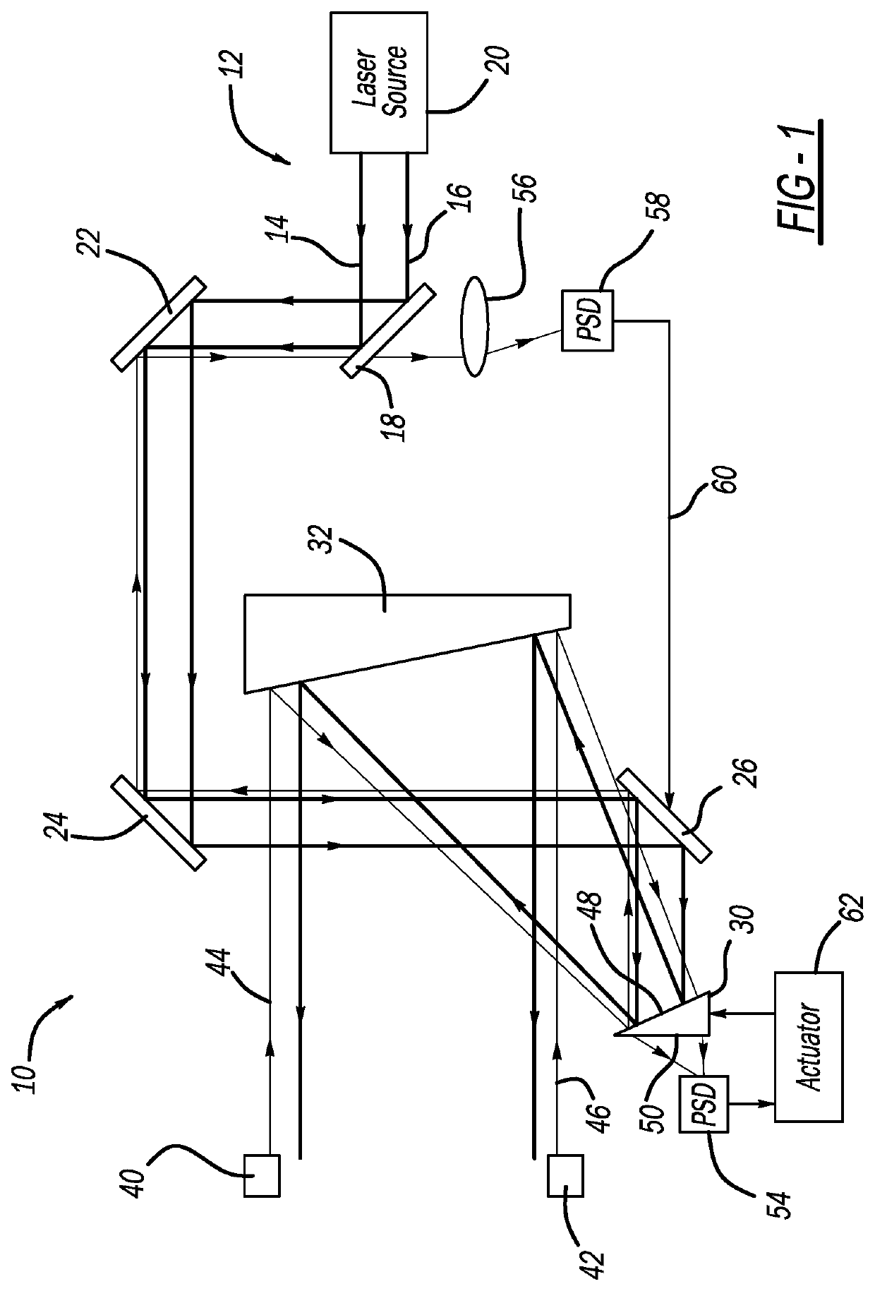
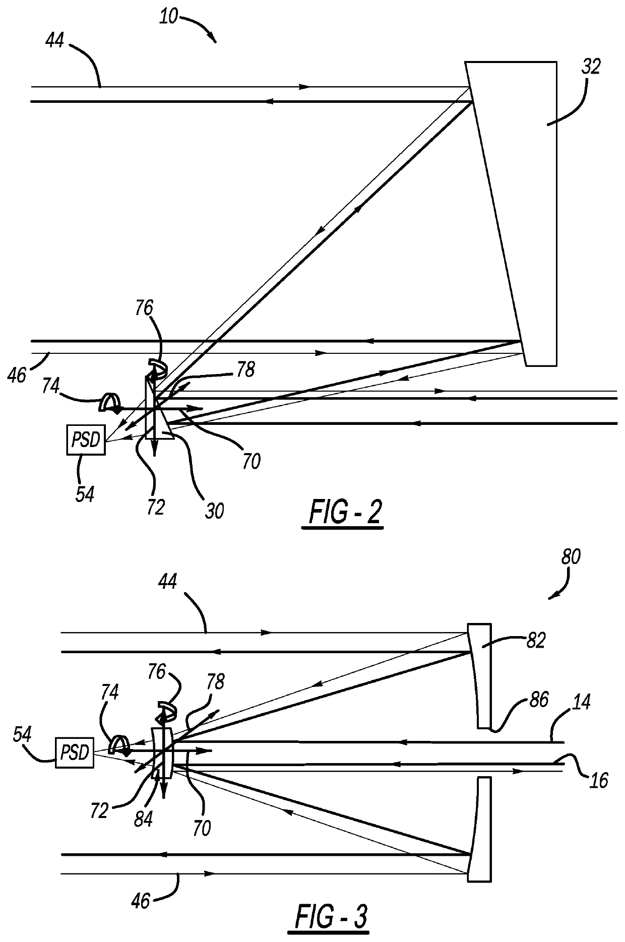
[0012]The following discussion of the embodiments of the disclosure directed to a beam directing telescope for use in a directed energy laser weapons system that employs active telescope component alignment is merely exemplary in nature, and is in no way intended to limit the invention or its applications or uses.

[0013]This disclosure describes a beam directing telescope that includes an alignment architecture for providing real-time sensing and correction of telescope component misalignment, independent from beam misalignment, where the telescope has particular application for use in a directed energy laser weapons system. The alignment architecture combines the coarse sensitivity reduction provided by passive alignment techniques and the fine sensitivity reduction provided by active alignment control. The active correction dynamically responds to the vibration profiles experienced by the telescope and corrects jitter-induced and low frequency sources of telescope misalignment. Act...


PUM


Abstract

A beam directing telescope for use in a directed energy weapons system that employs active telescope component alignment and that includes a primary mirror and a secondary mirror. The secondary mirror includes a first surface having a dichroic coating that reflects and directs a high energy laser beam to the primary mirror, reflects a portion of the reference beams and passes a portion of the reference beams that are focused by a second surface of the secondary mirror. A position sensing detector (PSD) is positioned relative to the secondary mirror such that the reference beams are focused as a spot on the PSD, where the PSD senses a position of the reference beams. An actuator changes the orientation of the secondary mirror to an alignment position if the position of the focused spots on the PSD is not the position for a desired alignment of the mirrors.

Description

BACKGROUNDField[0001]This disclosure relates generally to a beam directing telescope and, more particularly, to a beam directing telescope that is applicable to be used in a directed energy laser weapons system and that provides active telescope component alignment.Discussion of the Related Art[0002]Fiber laser amplifier systems that employ spectral beam combining (SBC) and coherent beam combining (CBC) architectures are often useful for directed energy (DE) laser weapons systems because of their high efficiency, high power scalability and excellent beam quality. In addition, the guided wave nature of light propagation in fiber enables packaging of beam combined fiber sources on fielded platforms. These types of weapons systems often employ beam director systems that reflect, expand, and point a high energy laser (HEL) beam to an intended target, where the director system includes a gimbaled telescope that points and directs the laser output beam to the target, and provides downstre...

Claims


Application Information

Patent Timeline
Patent Type & Authority Patents(United States)
IPC IPC(8): F41H13/00G02B23/06G02B27/40G02B26/08H01S3/00H01S3/067
CPCH01S3/06754G02B23/06G02B27/40F41H13/005H01S3/0071G02B26/0816G02B26/101H01S3/0014H01S3/005
Inventor DUPUIS, MICHAEL L.ROTHENBERG, JOSHUA E.MAKI, PHILIP H.FOO, GREGORY E.LIETO, CHRISTOPHER J.
Owner NORTHROP GRUMMAN SYST CORP
Why Eureka
Try Eureka