Control method for vehicle air conditioning, and vehicle air conditioning device

a technology for vehicle air conditioning and control method, which is applied in the direction of external condition input parameters, transportation and packaging, braking systems, etc., can solve the problems of insufficient the air conditioning will not stop, so as to ensure the air conditioning performance. , the effect of negative pressure inside the vacuum servo

Active Publication Date: 2021-01-26
NISSAN MOTOR CO LTD
View PDF17 Cites 1 Cited by
  • Summary
  • Abstract
  • Description
  • Claims
  • Application Information

AI Technical Summary

Benefits of technology

[0007]Consequently, when the predetermined condition has been established, negative pressure inside the vacuum servo can be ensured by stopping the air-conditioning compressor for a first time period. After the first time period has elapsed, the air-conditioning compressor is operated for a second time period regardless of the predetermined condition, and air-conditioning performance can therefore be ensured. After the second time period has elapsed, the air-conditioning compressor again stops for the first time period if the predetermined condition is established, and negative pressure inside the vacuum servo can therefore be ensured even if a brake pedal is repeatedly operated while the vehicle is traveling at a low speed. A vacuum servo negative pressure sensor is rendered unnecessary and costs can be reduced by estimating the negative pressure inside the vacuum servo.

Problems solved by technology

However, with the technology of Patent Citation 1, when the brake pedal is repeatedly operated while the vehicle is traveling at a low speed due to, for example, a traffic jam, etc., the start of the vehicle movement cannot be detected, and there is therefore a risk that the air conditioning will not stop and the negative pressure inside the vacuum servo will be insufficient.

Method used


Image

  • Control method for vehicle air conditioning, and vehicle air conditioning device
  • Control method for vehicle air conditioning, and vehicle air conditioning device
  • Control method for vehicle air conditioning, and vehicle air conditioning device

Examples


first embodiment

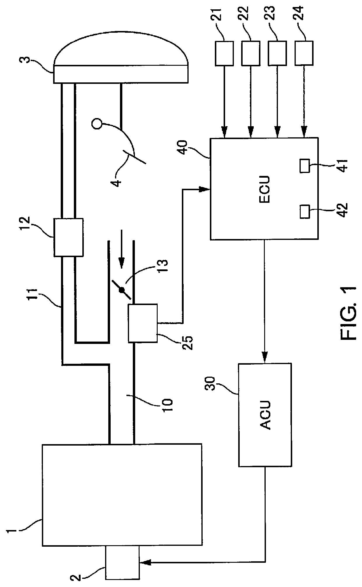
[0012]FIG. 1 is a system diagram of a vehicle to which a vehicle air-conditioning device for a vehicle of the first embodiment is applied. An engine 1, which is an internal combustion engine, takes in air from an intake manifold 10. The intake manifold 10 is provided with a throttle valve 13, which controls the amount of air taken in. A negative pressure supply passage 11 is connected to the intake manifold 10 between the throttle valve 13 and the engine 1, and an intake pressure sensor 25 is provided. The intake pressure sensor 25 detects negative pressure inside the intake manifold 10 (written hereinafter as PIM), and outputs the detected pressure to an engine control unit 40 (described hereinafter). The negative pressure supply passage 11 is connected to a vacuum servo 3.

[0013]The vacuum servo 3 is a negative pressure booster that assists a stepping force that is applied to a brake pedal 4 by introducing negative pressure into a pressure chamber. A check valve 12 is provided over...


PUM


Abstract

A vehicle air-conditioning device is provided for controlling a vehicle air-conditioning of a vehicle in accordance with a control method. A negative pressure, which is generated in an intake passage of the internal combustion engine by a vacuum servo that assists a brake pedal force, is estimated based on an atmospheric pressure and a pressure inside the intake passage. When a predetermined condition is established that includes a state in which the estimated negative pressure inside the vacuum servo is insufficient relative to a predetermined pressure during operation of the air-conditioning compressor, the air-conditioning compressor is stopped during a first time period, the air-conditioning compressor is operated during a second time period regardless of the predetermined condition after the first time period has elapsed, and operation of the air-conditioning compressor is controlled in accordance the states of the predetermined condition being established after the second time period has elapsed.

Description

CROSS-REFERENCE TO RELATED APPLICATIONS[0001]This application is a U.S. national stage application of International Application No. PCT / JP2017 / 018292, filed on May 16, 2017.BACKGROUNDTechnical Field[0002]The present invention relates to a control method for controlling air conditioning of a vehicle provided with an air-conditioning compressor, and to a vehicle air-conditioning device for a vehicle.Background Information[0003]A vehicle is disclosed in Japanese Laid-Open Patent Application No. 2014-136468 (Patent Citation 1) that has an air-conditioning compressor driven by an engine which is an internal combustion engine, and a vacuum servo in which negative pressure of an intake manifold of the engine is used to assist brake pedal force. Patent Citation 1 further discloses a technology in which when the negative pressure inside the vacuum servo is insufficient, the start of vehicle movement is a trigger to stop air conditioning for a predetermined amount of time, an engine load allo...

Claims


Application Information

Patent Timeline
Patent Type & Authority Patents(United States)
IPC IPC(8): B60W30/18B60H1/00B60W10/30B60W10/06B60W10/18B60T13/52
CPCB60W30/18181B60H1/00642B60T13/52B60W10/06B60W10/18B60W10/30B60W2510/06B60W2540/12B60W2555/20B60H1/3208B60H2001/3266B60H2001/3273B60T13/662B60T17/22
Inventor OHMURA, YASUSHIOOMORI, MASAHIROMORISHIMA, NOBUTOKATSUMA, SEIJI
Owner NISSAN MOTOR CO LTD
Why Eureka
Try Eureka