Transformer testing device, and method for testing a transformer

a transformer and testing device technology, applied in the direction of measurement devices, ac-ac conversion, instruments, etc., can solve the problems of increasing labor and time expenditure, etc., to achieve the effect of extensive automation of transformer testing, reducing time duration required for testing, and increasing the accuracy of characteristic variable determination

Active Publication Date: 2021-02-09
OMICRON ELECTRONICS GMBH
View PDF12 Cites 0 Cited by
  • Summary
  • Abstract
  • Description
  • Claims
  • Application Information

AI Technical Summary

Benefits of technology

[0005]There is a need for devices and methods with which a transformer test can be implemented efficiently and flexibly. In particular there is a need for devices and methods which allow a test of a three-phase transformer and which afford additional flexibility with regard to the outputting of test signals.
[0008]Such a transformer testing device makes it possible to achieve increased flexibility in the course of testing, since test signals from different sources can be allocated to a plurality of outputs in different ways. It is possible to perform a selective increase in the test signal for at least one of the phases by combination of a plurality of sources if this is desired for example with regard to a target accuracy of a measurement.
[0051]Different effects can be achieved with transformer testing devices, systems and methods according to exemplary embodiments. The time duration required for the test can be reduced. In particular, flexibility can be achieved without additional redistribution wirings.
[0052]Transformers having a multiplicity of different configurations are used in practice. The properties of the transformers vary accordingly. Transformer testing devices, systems and methods according to the exemplary embodiments make it possible to test a great diversity of transformers having a multiplicity of different configurations.
[0053]Transformer testing devices, systems and methods according to exemplary embodiments allow the accuracy of the determination of characteristic variables to be increased by measurement currents and / or measurement voltages being correspondingly adapted.
[0054]Transformer testing devices, systems and methods according to exemplary embodiments allow more extensive automation of transformer tests.

Problems solved by technology

In order to achieve flexibility when carrying out different measurements, redistribution wirings can conventionally be implemented, which increase the labor and time expenditure for the transformer test.
However, this entails the risk of faulty connections between transformer testing device and external unit and likewise leads to an increase in the labor and time expenditure.

Method used


Image

  • Transformer testing device, and method for testing a transformer
  • Transformer testing device, and method for testing a transformer
  • Transformer testing device, and method for testing a transformer

Examples


Embodiment Construction

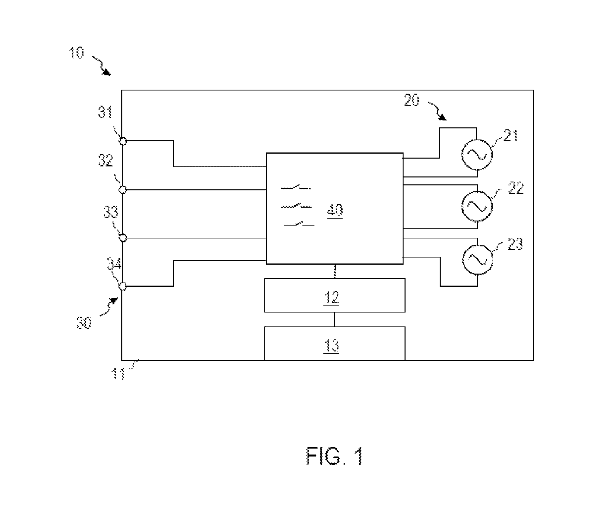
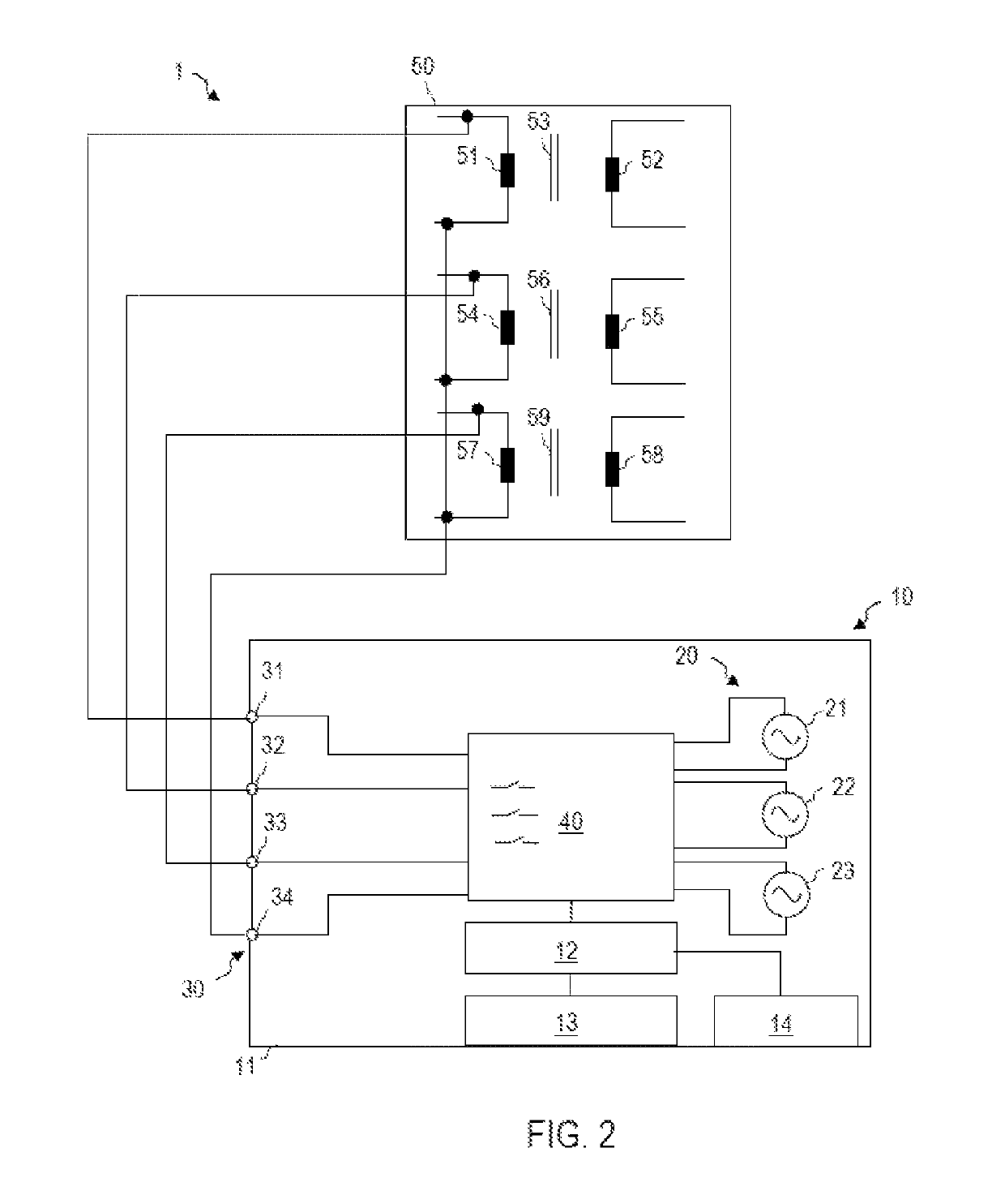
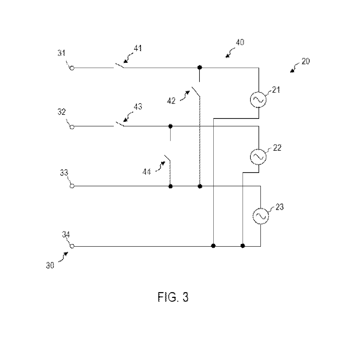
[0064]The present invention is explained in greater detail below on the basis of preferred embodiments with reference to the drawings. In the figures, identical reference signs designate identical or similar elements. The figures are schematic illustrations of various embodiments of the invention. Elements illustrated in the figures are not necessarily illustrated in a manner true to scale. Rather, the various elements illustrated in the figures are rendered in such a way that their function and their purpose become understandable to the person skilled in the art.

[0065]Connections and couplings between functional units and elements as illustrated in the figures can also be implemented as indirect connection or coupling. A connection or coupling can be implemented in a wired fashion or in a wireless fashion.

[0066]Devices and methods for carrying out a transformer test with a transformer testing device are described in detail below. The transformer can be a transformer for high- or me...


PUM


Abstract

A transformer testing device (10) comprises outputs (31-33) for detachably connecting the transformer testing device to windings of multiple phases of a transformer (50). The transformer testing device (10) further comprises a plurality of sources (21-23), each of which is designed to generate a test signal. The transformer testing device (10) also comprises a switching matrix (40) that is connected between the plurality of sources (21-23) and the outputs (31-33).

Description

FIELD OF THE INVENTION[0001]The invention relates to a transformer testing device, and to a method for testing transformers. The invention relates in particular to such devices and methods which are configured for testing a three-phase transformer.BACKGROUND[0002]Transformers are used as parts of power supply systems. Transformers can be used for voltage conversion from a first value on a high-voltage side to a second value, which is less than the first value, on a low-voltage side.[0003]The determination of properties of a transformer by a transformer test in which one or more characteristic variables of the transformer are ascertained by measurement is necessary for example for ensuring operational reliability, for driving, or for further reasons. Examples of such transformer tests include the determination of a static resistance, the determination of a dynamic resistance, the determination of a transmission ratio and / or the determination of a leakage impedance or leakage inductan...

Claims


Application Information

Patent Timeline
Patent Type & Authority Patents(United States)
IPC IPC(8): G01R31/02H02P13/00
CPCG01R31/027H02P13/00G01R31/62G01R31/50
Inventor FLAX, DIRKPÜTTER, MARKUS
Owner OMICRON ELECTRONICS GMBH
Why Eureka
Try Eureka