
Implant for bone segment fusion

a bone segment and implant technology, applied in the field of screws, can solve the problems of inability to reproduce similar clinical results, limited surgical options, and inability to operate at the same time, and achieve the effect of enhancing further bone growth

Active Publication Date: 2021-03-09
ANJALI INVESTMENTS LLC
View PDF12 Cites 5 Cited by
  • Summary
  • Abstract
  • Description
  • Claims
  • Application Information

AI Technical Summary

Benefits of technology

The invention provides a threaded implant for stabilizing, joining, or compressing bones, including fractures. It is made from titanium or tantalum metal and is designed to promote bone growth. The implant can have internal threads to support various medical devices. The thread design can include large pitch cancellous threads and smaller pitch cortical threads, or uniform threads throughout the implant.

Problems solved by technology

At the time diagnosis was made clinically, the surgical options were limited to rather large, open procedures.
The older literature suggested more than adequate rates of success with such procedures.
Subsequent authors, however, were unable to reproduce similar clinical results.
Given the extensive nature and dissection of the proposed surgical solutions, the procedures themselves were wrought with complications that included persistent pain and deep wound infections.
U.S. Pat. No. 6,053,916 discloses an implant with apertures on the body of the implant to allow for osseous ingrowth but does not disclose an implant having a porous structure and osteoconductive material coating for further bone growth enchantment.
However, none have the combination of being porous, fenestrated, surface treated, and coated with osteoconductive materials to enhance further bone growth.

Method used


Image

  • Implant for bone segment fusion
  • Implant for bone segment fusion
  • Implant for bone segment fusion

Examples


embodiment 100

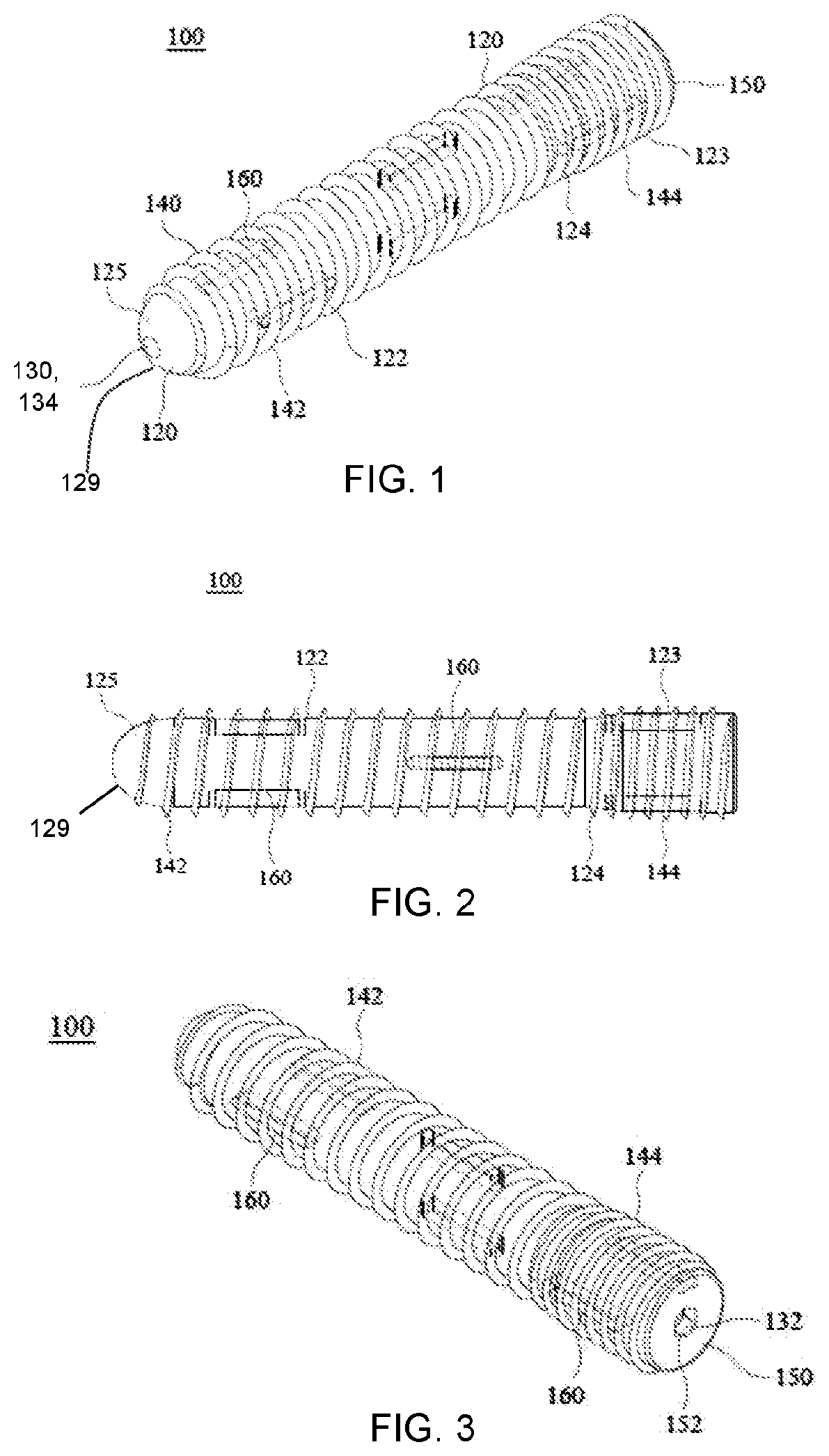
[0060]In the embodiment 100 illustrated in FIGS. 1-3, the helical threads 140 on the distal end of the implant are large pitch cancellous threads 142. In an embodiment, these threads may have a pitch of 2.75 mm and a thread height H of 2.00 mm. As shown in FIGS. 1-3, the forward 75% (approximately) of the implant employs cancellous threads, and the proximal remainder of the implant has smaller pitch cortical threads.

[0061]In the embodiment illustrated in FIGS. 1-3, the threads 140 on the proximal end of the implant are smaller pitch cortical threads 144. As illustrated, the cortical threads have a pitch of 1.75 mm and a thread height H of 1.50 mm.

[0062]In the embodiment illustrated in FIGS. 1-3, the implant body 120 does not have a uniform diameter. This is a function of the requirement that the cortical threads have a slightly larger overall diameter (Dmaj) than the cancellous threads. This is necessary because during implantation, the cortical threads follow the cancellous threads...

embodiment 102

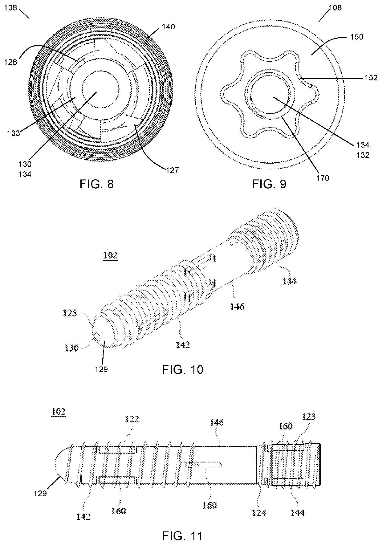
[0075]The embodiment 102 in FIGS. 10-11 is similar to FIGS. 1-3, except that this embodiment has a waist section 146 with no threads. Thus, there is a section of cancellous threads 142 on a distal portion of the body, and a section of cortical threads 144 on the proximal section of the body, and no threads in the center section. This type of implant may be used for compression of joints, including the SI joint.

embodiment 106

[0076]The embodiment 106 of FIGS. 12-13 has uniform thread dimensions and a uniform shaft diameter. In this embodiment as shown, the implant has cortical thread dimensions (144) throughout, but an alternative embodiment can have larger diameter cancellous threads throughout. FIGS. 10-13 are illustrated with blunt tip 125 / 129, but these embodiments are also possible with fluted tip 126 / 127.

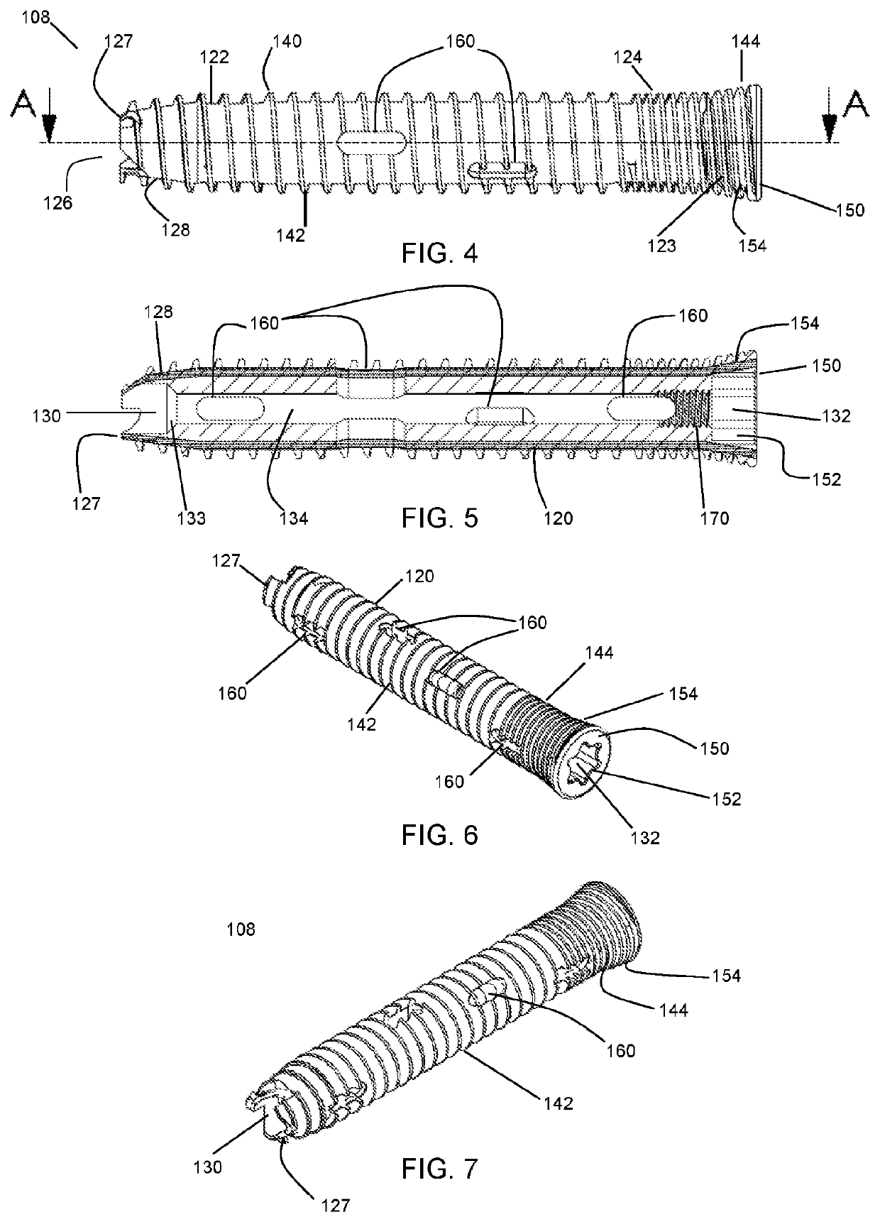
[0077]In an embodiment, the implants 100, 102, 106, and 108 may have perforations 160 for bone through-growth (also termed herein “fenestrations”). In an embodiment, the threads 140, 142, or 144 are interrupted over the fenestrations. In an alternative embodiment, the threads are continuous over the fenestrations. In an embodiment, the fenestrations 160 penetrate completely through the body of the implant latitudinally. In an embodiment, the fenestrations are slots or apertures, elongated in the longitudinal direction of the implant.

[0078]In a further embodiment, the implant may have a hollow core....


PUM

PropertyMeasurementUnit
porosityaaaaaaaaaa
pore sizesaaaaaaaaaa
lengthaaaaaaaaaa

Abstract

A bone screw implant is provided for immobilizing the articular surfaces of two bone segments by securing, fusing, or compression the two segments. The implant may be fabricated from a porous biocompatible metal and have a cylindrical shape and fully or partially threaded and may have variable pitch threads and a variable diameter of the shaft. The implant may include a blunt tip or a fluted self-drilling tip and a headless screwdriver socket. Large pitch cancellous threads may be in the leading-end portion of the cylinder shaft, and smaller pitch cortical threads may be at the trailing edge portion of the shaft. The implant may be fenestrated, it may have a roughened surface, and it may be coated with an osteoconductive material. The implant may be cannulated. In a specific embodiment, the implant is used for immobilizing the articular surfaces of a sacroiliac joint.

Description

CROSS REFERENCE TO RELATED APPLICATIONS[0001]This patent application claims priority under 35 U.S.C. § 120 to PCT International Patent Application No. PCT / US20 / 19194, filed Feb. 21, 2020, and to U.S. Patent Applications 62 / 808,454 filed Feb. 21, 2019, and 62 / 837,290 filed Apr. 23, 2019, the contents of which are incorporated by reference.FIELD OF THE INVENTION[0002]This invention pertains to screws for securing, fusing, and / or compressing the sacroiliac joint, vertebrae, and other bones, joints, or other bone segments.BACKGROUND OF THE INVENTION[0003]In orthopedics, there is frequently a need to stabilize bone segments as a result of fractures, joint dislocation, degenerative disease, or other causes. One approach to treating any of these conditions is the use of screws for securing, fusing, and / or compressing two bone segments together.[0004]One method of treating a fracture across two bone fragments is driving a compression screw across the fracture site. Some compression screws m...

Claims


Application Information

Patent Timeline
Patent Type & Authority Patents(United States)
IPC IPC(8): A61F2/30A61B17/70
CPCA61F2/30771A61B17/7032A61F2/30988A61F2002/3085A61F2002/30224A61F2002/30622A61F2002/30863A61F2002/30886A61F2002/30995A61F2310/00023A61F2310/00131A61F2310/00796A61L27/06C22C14/00C22C27/02A61F2002/3092A61F2002/30777A61L2430/02A61L27/56A61L27/32A61B17/866A61B17/863A61B17/864A61B17/8615A61B17/7055A61B17/7098A61B17/8645A61B17/8635
Inventor PATEL, AMIT
Owner ANJALI INVESTMENTS LLC
Learn More