Apparatus and method for vacuumizing and sealing a package

a vacuum sealing and apparatus technology, applied in packaging, packaging cheese, liquid/fluent solid measurement, etc., can solve the problems of reducing the service life of the current vacuum packing apparatus, and reducing the service life of the vacuum chamber. , to achieve the effect of reducing the operational footprint, facilitating the loading and/or unloading of packages, and consolidating the overall operational footprin

Active Publication Date: 2021-03-09
FURUKAWA MFG +1
View PDF47 Cites 1 Cited by
  • Summary
  • Abstract
  • Description
  • Claims
  • Application Information

AI Technical Summary

Benefits of technology

[0009]Various embodiments provide an apparatus for vacuumizing and sealing packages having a reduced operational footprint by providing a platen travel path extending around a single axis of rotation, and providing one or more linear travel portions of the platen travel path to facilitate loading and / or unloading of packages onto and / or off of the platens travelling along the platen travel path of the apparatus having a consolidated overall operational footprint.

Problems solved by technology

Due at least in part to timing requirements for removing air from within a package, cycle speeds of current vacuum packing apparatuses are often limited.
It has been found that the endless chain may stretch over time, which complicates achieving proper alignment and positioning of the platens and vacuum chambers in the system.

Method used


Image

  • Apparatus and method for vacuumizing and sealing a package
  • Apparatus and method for vacuumizing and sealing a package
  • Apparatus and method for vacuumizing and sealing a package

Examples


Embodiment Construction

[0096]The present invention will now be described more fully hereinafter with reference to the accompanying drawings, in which some, but not all embodiments of the invention are shown. Indeed, the invention may be embodied in many different forms and should not be construed as limited to the embodiments set forth herein. Rather, these embodiments are provided so that this disclosure will satisfy applicable legal requirements. Like numbers refer to like elements throughout.

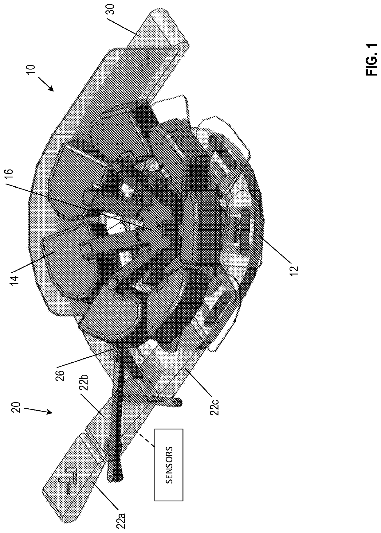
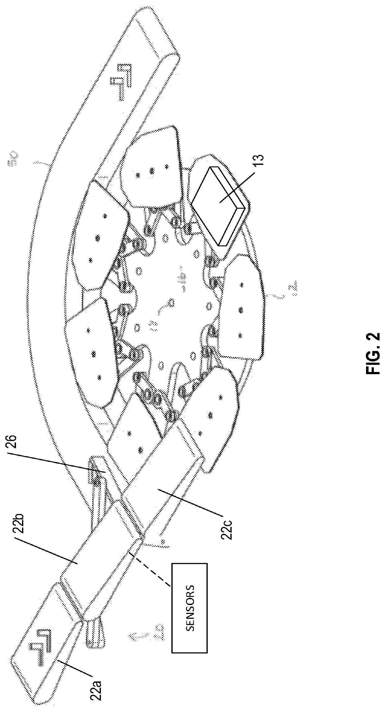
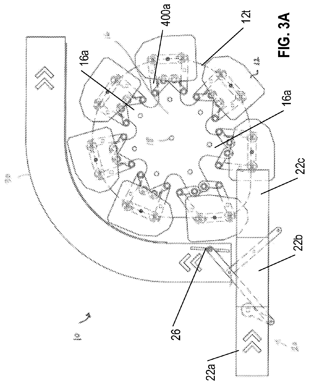
[0097]A rotary food packager configured to vacuumize and heat seal packages is described herein. The packages may be, for example, plastic bags each containing a product (e.g., a food product, such as a meat product). In various embodiments, the rotary food packager has a plurality of package platens configured to support a pre-bagged product and a plurality of corresponding vacuum chambers. In various embodiments, the package platens and the vacuum chambers rotate synchronously around a single, vertical axis of ro...


PUM

PropertyMeasurementUnit
rotationaaaaaaaaaa
vacuum pressureaaaaaaaaaa

Abstract

An apparatus (10) for vacuumizing and sealing a package (322) includes a plurality of platens (12) and vacuum chambers (14), each chamber (14) adapted to mate with a dedicated one of the platens (12); a conveying system (16) for conveying the platens (12) and chambers (14) along a generally angular path having a single axis of rotation (18); an automated loading assembly (20) having a linear component (22c) and configured to load a package (322) onto each of the platens (12); an automated unloading assembly (26) having a linear portion and configured to unload a vacuumized, sealed package (322) from each loaded platen (12) onto an outfeed conveyor (30); and a vacuumizing / sealing system configured to cause relative movement of each chamber (14) / platen (12) pair, along a portion of the angular path, to form therebetween an air-tight enclosure accommodating the package (322) and effect vacuumization and sealing of the package (322).

Description

CROSS REFERENCE TO RELATED APPLICATIONS[0001]This application is a National Stage Application, filed under 35 U.S.C. 371, of International Application No. PCT / US2016 / 053279, filed Sep. 23, 2016, which claims priority to U.S. Provisional Application No. 62 / 232,856, filed Sep. 25, 2015; the contents of both of which are hereby incorporated by reference in their entirety.BACKGROUNDRelated Field[0002]The present application describes apparatuses and methods for vacuumizing and sealing a package. The described apparatuses and methods may be used to vacuumize and seal a bagged products, including food products (e.g., poultry, cheese, red meat, smoked food products, processed food products, ready to eat food products, and / or the like).DESCRIPTION OF RELATED ART[0003]Vacuum packaging in heat sealable plastic bags has been used for packaging food products, such as poultry, meat, and cheese. A vacuum packaging process generally involves placing the food product into a heat sealable plastic ba...

Claims


Application Information

Patent Timeline
Patent Type & Authority Patents(United States)
IPC IPC(8): B65B25/06B65B31/02B65B51/14B65B59/02F16K51/02F16K3/02F16K3/18B29C65/22B29C65/00B29C65/74B29C65/38B29C65/78G01F17/00G01F22/00B29L31/00
CPCF16K51/02B29C65/223B29C65/224B29C65/38B29C65/7451B29C65/7885B29C66/00145B29C66/1122B29C66/244B29C66/2442B29C66/30621B29C66/43121B29C66/73921B29C66/82421B29C66/8322B29C66/849B65B25/067B65B25/068B65B31/022B65B51/146F16K3/029F16K3/0254F16K3/184B29C66/71B29C66/723B29C66/7234B29C66/72341B29L2031/7128B65B31/024G01F17/00G01F22/00B65B31/04B65B7/02B65B51/22B65B53/02B65B57/04B65B61/06G01B11/00B29C66/232B29C66/949B29K2023/00B29K2023/04B29K2023/08B29K2023/12B29K2067/00B29K2077/00B29K2027/08B29K2023/086B29K2029/04B29K2033/20B65B59/02B65B25/001B65B65/02B65D65/38B65D2565/381
Inventor MCDONALD, GREGORY E.GROSSMAN, GREGORY H.PRICE, JOE A.HODGSON, RODKING, JR., JOHN L.NAKAMOTO, SHUICHINII, YOSHITAKAROHRER, SILVIOCAILLIER, JOELSCHMALZ, PETER
Owner FURUKAWA MFG
Why Eureka
Try Eureka