Battery and battery manufacturing method

a battery and manufacturing method technology, applied in the direction of cell components, final product manufacturing, sustainable manufacturing/processing, etc., can solve the problems of requiring a comparatively expensive facility for joining together the internal terminal and the external terminal by laser welding, and achieve the effect of reducing the likelihood of a phenomenon, reducing the electrical resistance, and high quality of the conduction path

Active Publication Date: 2021-03-16
TOYOTA JIDOSHA KK
View PDF18 Cites 0 Cited by
  • Summary
  • Abstract
  • Description
  • Claims
  • Application Information

AI Technical Summary

Benefits of technology

[0004]A welded portion between an internal terminal and an external terminal tends to have lower electrical resistance than other contact portions between the internal terminal and the external terminal, and thus can form a main conduction path between the internal terminal and the external terminal. When the welded portion is located at an outer circumferential edge of a swaged portion, for example, a foreign object etc. can come in contact with this welded portion. To maintain high quality of the conduction path between the internal terminal and the external terminal, it is desirable to reduce the likelihood of the phenomenon that a foreign object comes in contact with the welded portion between the internal terminal and the external terminal. Moreover, joining together the internal terminal and the external terminal by laser welding requires a comparatively expensive facility such as a laser welding machine. Therefore, the present disclosure proposes a battery having a whole new structure and a manufacturing method of this battery.
[0005]A battery according to a first aspect of the present disclosure includes a battery case component having a mounting hole, an internal terminal, an external terminal, and an insulation member. Here, the insulation member is interposed between the internal terminal and the battery case component and interposed between the external terminal and the battery case component. The internal terminal includes a base part that is laid on the inner side of the battery case component with the insulation member interposed between the base part and the battery case component, and a projecting part that protrudes from the base part and is fitted on the battery case component by being inserted through the mounting hole with the insulation member interposed between the projecting part and an inner periphery of the battery case component defining the mounting hole. The external terminal is laid on the projecting part inserted through the mounting hole, and includes a weld at which the external terminal is welded to the projecting part of the internal terminal. The battery with this structure has the weld at a position where the external terminal is laid on the projecting part of the internal terminal, which can reduce the likelihood that a foreign object etc. from outside comes in contact with the weld.
[0010]Here, in the assembly step of assembling the internal terminal, the gasket, the battery case component, the insulator, and the external terminal, a state is established where the cylindrical part of the gasket is fitted in the mounting hole of the battery case component, the projecting part of the internal terminal is fitted in the cylindrical part of the gasket, the insulator is disposed on an outer surface of the battery case component with the projecting part fitted in the through-hole, and the external terminal is disposed on top of the insulator so as to lie on the projecting part. Next, the external terminal is pressed against the projecting part of the internal terminal, and the external terminal or the internal terminal is vibrated to thereby weld together the projecting part and the external terminal in a solid state. This method uses a solid-state welding machine that is inexpensive compared with a laser welding machine in the welding step for forming a conduction path between the internal terminal and the external terminal, and therefore can keep down the facility cost in the welding step for forming a conduction path between the internal terminal and the external terminal.

Problems solved by technology

Moreover, joining together the internal terminal and the external terminal by laser welding requires a comparatively expensive facility such as a laser welding machine.

Method used


Image

  • Battery and battery manufacturing method
  • Battery and battery manufacturing method
  • Battery and battery manufacturing method

Examples


Embodiment Construction

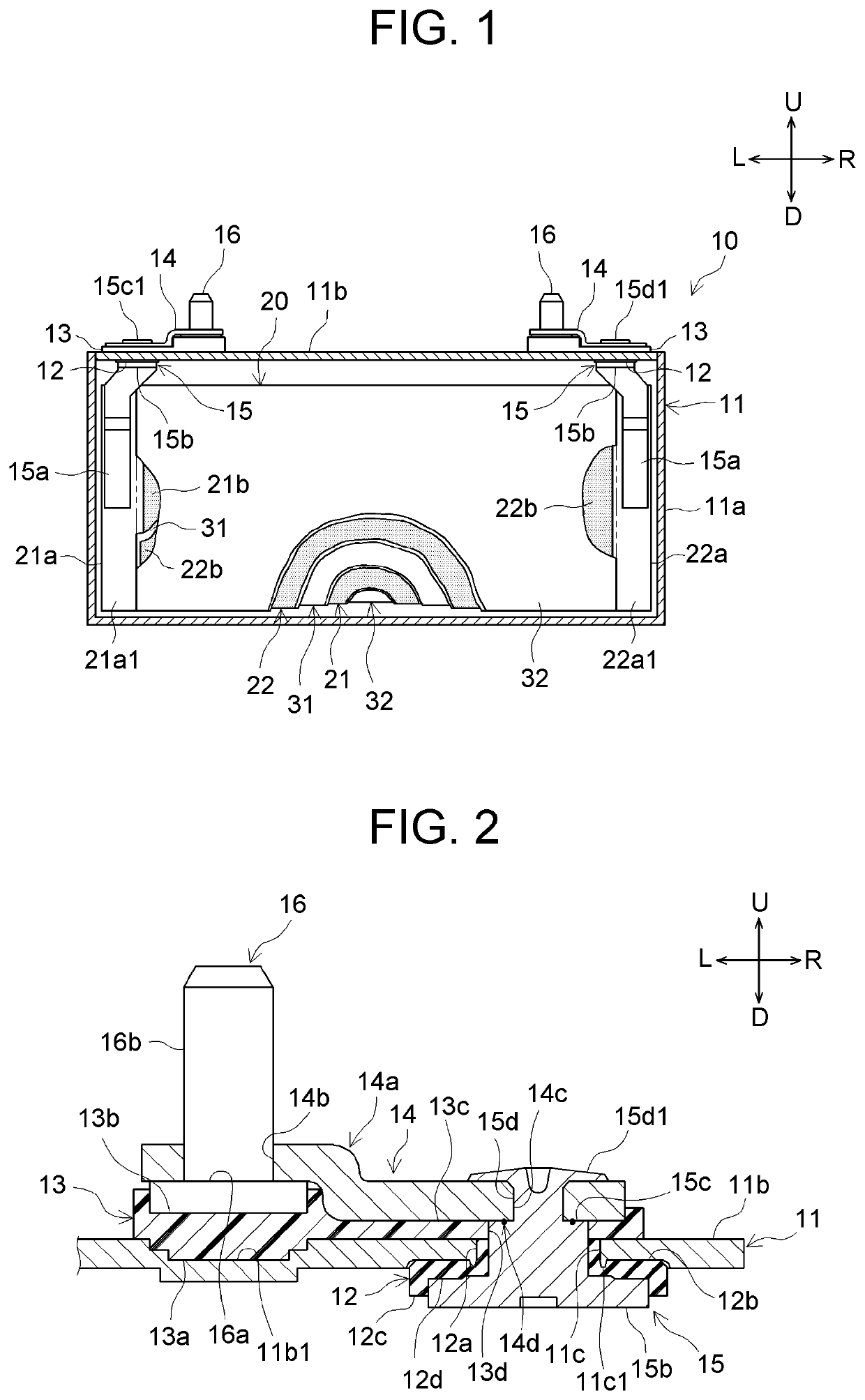
[0025]An embodiment of a battery and a battery manufacturing method proposed herein will be described below. It should be understood that the embodiment described herein is not intended to particularly limit the present disclosure. Unless otherwise mentioned, the present disclosure is not limited to the embodiment described herein. The drawings are schematic and do not necessarily reflect actual objects. Those members and portions that have the same effects are denoted by the same reference sign as appropriate to omit redundant description. Upward, downward, leftward, rightward, frontward, and rearward directions are indicated in the drawings by the arrows U, D, L, R, F, and Rr, respectively.

[0026]Here, the battery and the battery manufacturing method will be described by using a sealed battery 10 shown in FIG. 1 and FIG. 2 as an example. FIG. 1 is a partial sectional view of the sealed battery 10 according to the embodiment of the present disclosure. FIG. 1 shows a state where an i...


PUM

PropertyMeasurementUnit
holding forceaaaaaaaaaa
areaaaaaaaaaaa

Abstract

A battery manufacturing method includes assembling an internal terminal, a gasket, a battery case component, an insulator, and an external terminal into a state where a cylindrical part of the gasket is fitted in a mounting hole of the battery case component, a projecting part of the internal terminal is fitted in the cylindrical part of the gasket, the insulator is disposed on an outer surface of the battery case component with the projecting part fitted in a through-hole, and the external terminal is disposed on top of the insulator so as to lie on the projecting part. The external terminal is pressed against the projecting part of the internal terminal, and the external terminal or the internal terminal is vibrated to thereby weld together the projecting part and the external terminal in a solid state.

Description

INCORPORATION BY REFERENCE[0001]The disclosure of Japanese Patent Application No. 2017-196426 filed on Oct. 6, 2017 including the specification, drawings and abstract is incorporated herein by reference in its entirety.BACKGROUND1. Technical Field[0002]The present disclosure relates to a battery and a battery manufacturing method.2. Description of Related Art[0003]Japanese Patent Application Publication No. 2014-11073 discloses a method in which a shaft part of an internal terminal is inserted through a battery case and an external terminal and swaged onto the external terminal, and then an outer circumferential edge of a swaged portion is laser-welded to the external terminal. Japanese Patent Application Publication No. 2017-84585 discloses a method in which beads are provided by laser welding along an outer circumferential edge of a swaged portion.SUMMARY[0004]A welded portion between an internal terminal and an external terminal tends to have lower electrical resistance than othe...

Claims


Application Information

Patent Timeline
Patent Type & Authority Patents(United States)
IPC IPC(8): H01M2/30H01M50/543H01M10/058H01M10/0525H01M50/116H01M50/183H01M50/528H01M50/545H01M50/119H01M50/176H01M50/184H01M50/188H01M50/193H01M50/55H01M50/553H01M50/566
CPCH01M50/543H01M10/058H01M10/0525H01M50/116H01M50/183H01M50/528H01M50/545H01M50/553H01M50/193H01M50/55H01M50/176H01M50/566H01M50/188H01M50/119H01M50/184Y02E60/10Y02P70/50H01M50/172H01M10/052
Inventor HAGINO, TOMOTAKANEMOTO, YUTAONO, TOMOHIRONARUSE, YOICHI
Owner TOYOTA JIDOSHA KK
Why Eureka
Try Eureka