Wind turbine blade manufacture

a technology of wind turbine blades and blades, which is applied in the direction of motors, applications, domestic objects, etc., can solve the problems of difficult and time-consuming shear web positioning, and adversely affecting the resulting bondlin

Active Publication Date: 2021-03-23
VESTAS WIND SYST AS
View PDF52 Cites 0 Cited by
  • Summary
  • Abstract
  • Description
  • Claims
  • Application Information

AI Technical Summary

Benefits of technology

[0020]The method of the present invention is a repeatable process that creates consistently well-defined bondlines. The bondline is defined by the dimensions of the primary cavity, which is filled with adhesive. Wastage of adhesive is eliminated because the adhesive is contained within the primary cavity and there is no ‘squeeze out’ of adhesive. Accordingly, the material cost of the adhesive and the overall weight of the blade is reduced in comparison to the prior art bonding process.
[0021]As the shear web is in position before injection of the adhesive, the risk of the adhesive curing before the web is loaded into the blade and positioned correctly is eliminated. This allows more time to position the web correctly before the bonding process takes place. Also, this allows different adhesives to be used, for example a more reactive adhesive having a faster curing time can be used in the present method.
[0022]As the adhesive in the present method does not make contact with the air, the risk of carbamation is avoided. Contact between operators and the adhesive is also advantageously eliminated in the present method because adhesive is injected into the sealed cavity. Accordingly, this reduces any risks to personnel associated with handling adhesive.
[0023]The method may comprise providing one or more spacer elements in the primary cavity between the mounting flange and the inner surface of the blade shell. The spacer elements are preferably configured to maintain the mounting flange and the inner surface of the blade in spaced apart relation when a vacuum is created in the primary cavity. This advantageously keeps the primary cavity open and prevents the mounting flange being pulled too close to the inner surface of the blade shell. The spacers also conveniently set the bond height between the shear web and the blade shell. The spacers are preferably made from substantially incompressible material such as wood, plastic or metal.
[0029]Preferably the method comprises reducing the pressure in the peripheral cavity to a lower level than in the primary cavity so as to create a stronger vacuum in the peripheral cavity than in the primary cavity. Advantageously the vacuum in the peripheral cavity serves as a clamp around the primary seal and reacts the pressure of the adhesive injected into the primary cavity. This reduces the likelihood of the primary seal being broken by the adhesive pressure. Any air ingress in the process will also be removed via the peripheral cavity and hence away from the bondline.
[0030]The method may advantageously comprise monitoring the pressure in the peripheral cavity and detecting the presence of a leak in the primary seal in the event of a sudden change in the monitored pressure. The pressure can advantageously be monitored at a location remote from the shear web, for example at a remotely-located vacuum pump, thus allowing remote monitoring and control of the process.

Problems solved by technology

However, it can be difficult and time consuming to position the shear webs 24 correctly, and if the adhesive cures partially in the meantime its viscosity will increase and this may adversely affect the resulting bondlines between the shear webs 24 and the blade shells 12, 14.
Adhesives such as epoxy, which is typically used in the above process, can adversely react with moisture and carbon dioxide in the air in a process known as ‘carbamation’.
If this happens, a greasy residue may develop on the adhesive, which may compromise the strength of the bonded joints.
Epoxy and many other adhesives may also present a handling hazard to workers.
This adhesive is effectively wasted, yet it still contributes to the overall weight of the completed wind turbine blade, and represents a substantial material cost.

Method used


Image

  • Wind turbine blade manufacture
  • Wind turbine blade manufacture
  • Wind turbine blade manufacture

Examples


Embodiment Construction

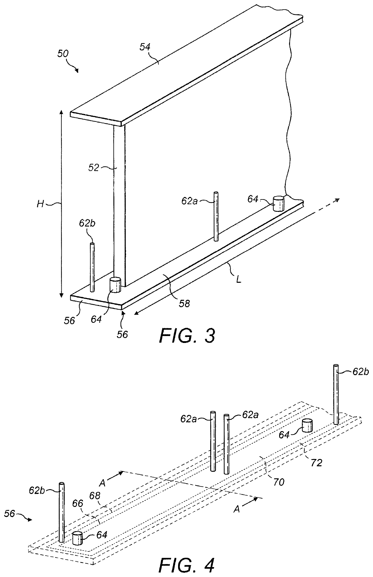
[0050]Referring to FIG. 3, this shows a first end of a longitudinally-extending shear web 50 according to an embodiment of the present invention. The shear web 50 is approximately 80 metres in length (L) and varies in height (H) along its length, with a maximum height at one end of about 4.5 metres. The shear web 50 is substantially I-shaped in cross section and comprises a substantially vertical web 52 disposed between upper and lower mounting flanges 54, 56. The mounting flanges 54, 56 are arranged substantially perpendicular to the web 52 in this example, i.e. substantially horizontal.

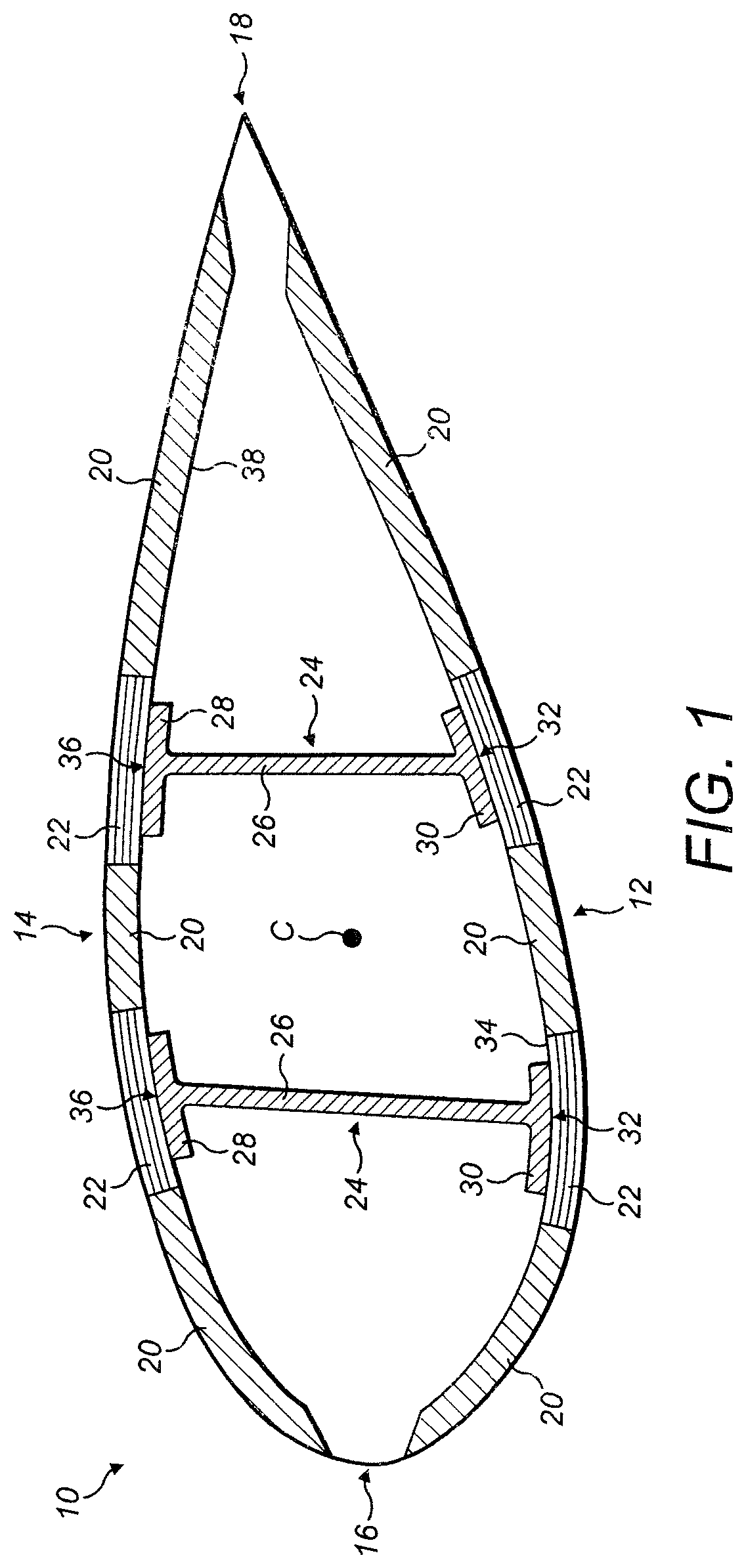
[0051]The lower mounting flange 56 comprises an inner surface 58 and an outer surface 60. The terms ‘inner’ and ‘outer’ are relative to a central longitudinal axis of a wind turbine blade in which the shear web 50 is affixed in use (e.g. the central longitudinal axis (C) of the blade 10 in FIG. 1, which extends perpendicular to the page in FIG. 1). The outer surface 60 of the lower mounting flange 5...


PUM

PropertyMeasurementUnit
heightaaaaaaaaaa
lengthaaaaaaaaaa
pressureaaaaaaaaaa

Abstract

Method of bonding a shear web (50) to a wind turbine blade shell (75) and the obtained blade, wherein the shear web (50) comprises a web and a mounting flange (56) oriented transverse to the web (50). The method involves: providing a seal (66, 68) on the mounting flange (56) of the shear web (50) such that when the mounting flange (56) is positioned against the blade shell (75), a cavity (76) is defined by the seal between the mounting flange (56) and the blade shell (75). The air of the cavity (76) is then evacuated and adhesive is injected into the cavity (76). The use of pieces (80) to keep the distance between the mounting flange (56) and the blade shell (75) is preferred.

Description

TECHNICAL FIELD[0001]The present invention relates generally to the manufacture of wind turbine blades, and more specifically to an improved method of bonding a shear web to a wind turbine blade shell.BACKGROUND[0002]Wind turbine blades, such as the long blades employed on modern utility-scale wind turbines, generally comprise a substantially hollow blade shell made primarily of composite materials, such as glass-fibre reinforced plastic. Referring to FIG. 1, this shows a cross-sectional view of a known wind turbine blade 10. The blade shell is made up of two half shells, a windward shell 12 and a leeward shell 14, which are bonded together along the leading edge 16 and trailing edge 18 of the respective half shells 12, 14. Each half shell 12, 14 is made up of a plurality of glass-fibre fabric layers and other structural components such as foam core material 20 and carbon fibre reinforcements 22.[0003]A pair of shear webs 24 are bonded between the respective half shells 12, 14. The ...

Claims


Application Information

Patent Timeline
Patent Type & Authority Patents(United States)
IPC IPC(8): F03D1/06B29C65/48B29C65/54B29C65/78B29C65/00B29L31/08
CPCF03D1/0675B29C65/483B29C65/542B29C65/7826B29C65/7841B29C66/00145B29C66/112B29C66/1142B29C66/131B29C66/301B29C66/324B29C66/524B29C66/5326B29C66/54B29C66/61B29C66/636B29C66/721B29C66/9241B29C66/7212B29L2031/085F05B2230/23F05B2280/6003Y02E10/72Y02P70/50B29C66/532B29K2309/08B29C65/544
Inventor SMITH, JONATHANWARDROPPER, STEVE
Owner VESTAS WIND SYST AS
Why Eureka
Try Eureka