Unlock instant, AI-driven research and patent intelligence for your innovation.

Coupling device

Active Publication Date: 2021-03-30
ZEITFRACHT GMBH & CO KGAA
View PDF21 Cites 0 Cited by
  • Summary
  • Abstract
  • Description
  • Claims
  • Application Information

AI Technical Summary

Benefits of technology

The invention aims to improve coupling devices in a way that allows for higher torque moments, particularly when using powerful direct drives as drive units with tool turrets. This will provide greater efficiency and performance in transferring power.

Problems solved by technology

Such transfer is not possible with the described current gearing solutions, which use gearing on smaller diameters for machining.

Method used


Image

  • Coupling device
  • Coupling device
  • Coupling device

Examples


Embodiment Construction

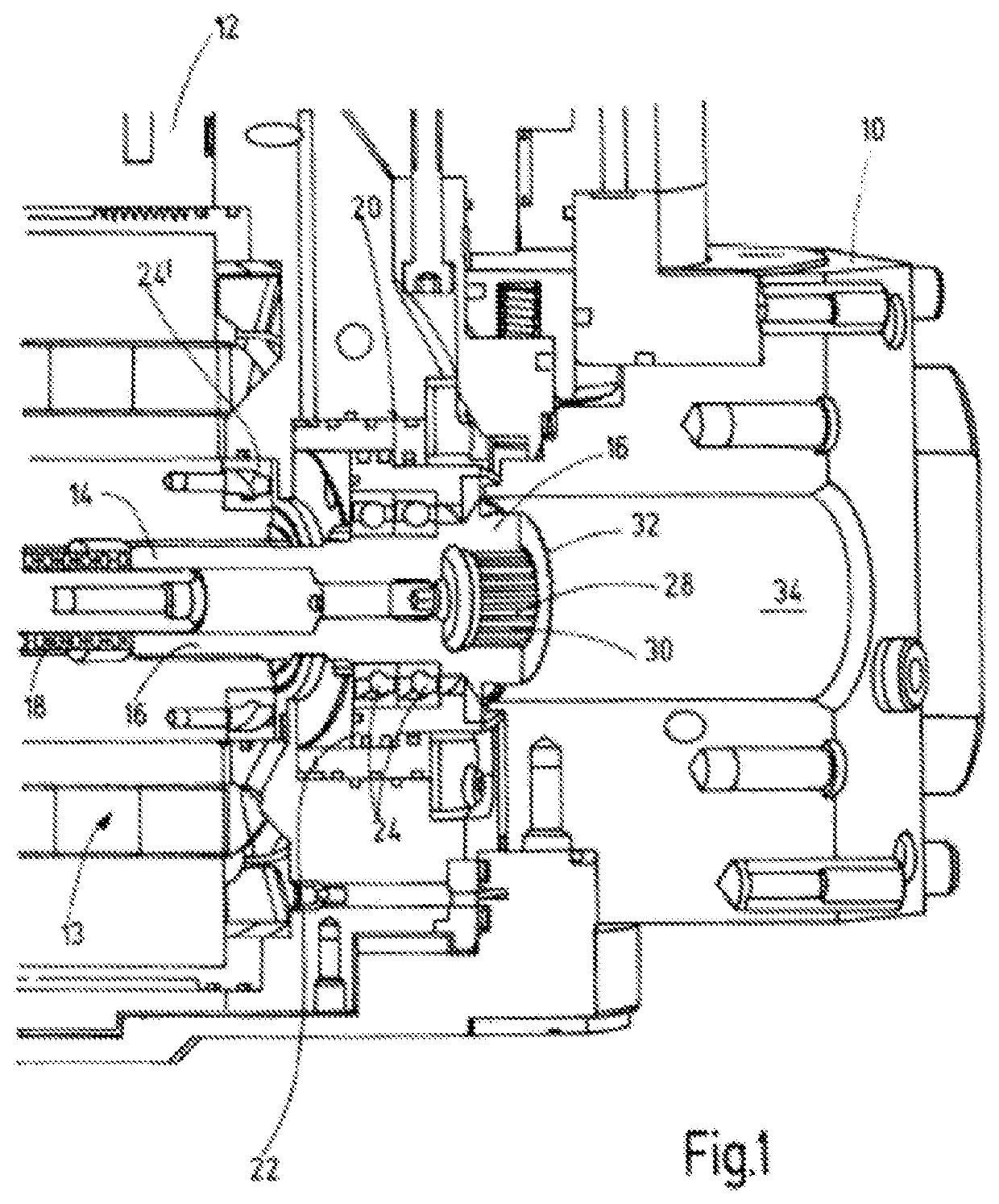
[0018]The FIG. 1 depicts parts of a tool turret for a machine tool (not shown), wherein the tool turret is part of the machine, for example, in form of a milling machine for the machining of a work piece. To this end, a tool holder disk 10 is pivotally or rotationally guided around stationary housing components 12 of the tool turret which, in modern direct-concept drives, accept a drive unit 13 with a drive shaft 14 for the tool turret. The drive unit 13, which is usually in form of an electromotor, is preferably an integral component of the stationary housing components 12 of the tool turret, and solutions of this kind are disclosed in, for example, DE 101 30 446 A1, DE 10 2009 042 772 A1 or in DE 10 2005 033 890 A1. The drive shaft 14 is in the usual manner rotatably supported by commonly used bearings 24, 24′ (not described in detail) inside the housing components 12, is provided in multiple sections and comprises a frontal engagement part 16. Frontal engagement part 16 may be mo...


PUM

PropertyMeasurementUnit
Pressureaaaaaaaaaa
Circumferenceaaaaaaaaaa
Displacementaaaaaaaaaa

Abstract

A coupling device is for the reversible establishment of a drive connection between a driving unit (13) of a tool turret and a driven unit (46) of a tool receptacle (36) attached to the tool turret and in which a machining tool is able to be received. In a coupling position, a drive shaft (14) of the driving unit (13) is engaged by way of its external toothing (32) with an internal toothing of a driven shaft (44) of the driven unit (46). For a collision-free orientation of the external toothing (32) with respect to the internal toothing, before coupling, an aligning device is used. The orienting device passes through parts of the driven shaft (44) and has a control on one side for the cooperation with the drive shaft (13) and an aligner that is actuable by the control on the other side. The aligner is securable to the tool receptacle.

Description

FIELD OF THE INVENTION[0001]The invention concerns the detachable engagement of a drive connection between a drive unit of a tool turret and an output unit of a tool holder that is attached to the tool turret. A machining tool may be retained in the tool holder. The invention concerns a tool turret as well as a tool holder comprising at least parts of such a coupling device.BACKGROUND OF THE INVENTION[0002]DE 10 2009 042 772 A1 discloses a drive device for selectively driving a tool holder disk of a tool turret and at least one machining tool, which is attached to the tool holder disk by a tool holder, which may be driven by two drives that have a common drive device comprising a drive shaft. The drives are connectable with one another via a coupling device that may be controlled by at least one operating device each. The drives have the purpose of driving the tool holder disk or the machining tool. At least the drive device together with the drives are disposed inside the tool hold...

Claims


Application Information

Patent Timeline
IPC IPC(8): B23B29/32B23Q5/20B23Q3/12
CPCB23Q3/12B23Q5/20B23B29/32B23Q2220/002Y10T29/5155Y10T29/5167
Inventor GIESLER, STEFFENSTROBEL, ANDREA
Owner ZEITFRACHT GMBH & CO KGAA
Features
  • R&D
  • Intellectual Property
  • Life Sciences
  • Materials
  • Tech Scout
  • Unparalleled Data Quality
  • Higher Quality Content
  • 60% Fewer Hallucinations
Learn More