Vertical tail unit for flow control

a flow control and vertical tail technology, applied in the direction of airflow influencers, boundary layer controls, aircraft stabilisation, etc., can solve the problems of increasing drag at the vertical tail unit and reducing efficiency, and achieve the effect of reducing drag and increasing efficiency

Active Publication Date: 2021-04-06
AIRBUS OPERATIONS GMBH
View PDF112 Cites 0 Cited by
  • Summary
  • Abstract
  • Description
  • Claims
  • Application Information

AI Technical Summary

Benefits of technology

[0009]An invention has been made and is disclosed herein that may be embodied as a vertical tail unit with reduced drag an increased efficiency.
[0010]An embodiment of the invention is a vertical tail unit having an air inlet is formed as an opening that is arranged in one lateral side of the outer skin and that is flush with the outer skin, in particular with the outer mold line. The opening might be formed as a hole in the outer skin with a channel following to the inside of the vertical tail unit. In such a way, no parts of the air inlet project out from the outer skin into the ambient air flow so that no additional drag is caused by the air inlet or at least the additional drag is minimized.
[0013]According to a further embodiment, the air inlet has two opposite side walls between which the door moves when pivoting between the opened and closed positions. The side walls proceed in a diverging manner with respect to one another in a direction from the leading edge to the trailing edge, i.e. along the channel from the hinge to the inlet duct. In particular, the side walls may proceed in the form of a wave in the direction from the leading edge to the trailing edge such that the distance between the side walls first increases with an increasing slope and subsequently increases with a decreasing slope. By such geometry of the side walls particularly advantageous mass flow rate and flow conditions can be obtained.

Problems solved by technology

However, such an air scoop causes additional drag at the vertical tail unit and decreases efficiency.

Method used


Image

  • Vertical tail unit for flow control
  • Vertical tail unit for flow control

Examples


Embodiment Construction

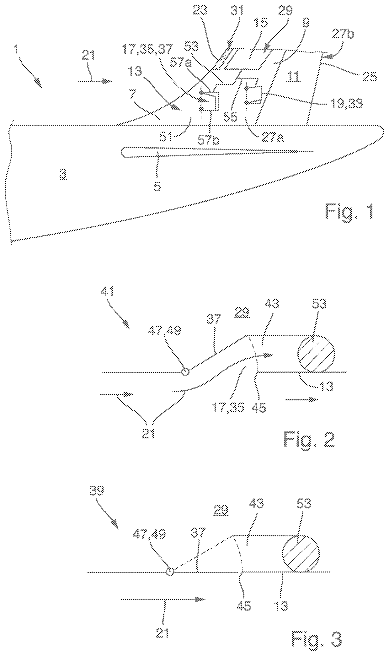
[0023]In FIG. 1 an embodiment of an aircraft 1 according to the invention is illustrated. The aircraft 1 comprises a fuselage 3, a horizontal tail unit 5, and a vertical tail unit 7 according to an embodiment of the invention. The vertical tail unit 7 comprises a vertical stabilizer 9 and a rudder 11 pivotally mounted to the vertical stabilizer 9. The vertical tail unit 7 is configured for hybrid laminar flow control and comprises an outer skin 13, a pressure chamber 15, an air inlet 17, and an air outlet 19.

[0024]The outer skin 13 is in contact with an ambient air flow 21 and extends between a leading edge 23 and a trailing edge 25. Further, the outer skin 13 has two opposite lateral sides 27a, 27b and surrounds an interior space 29. The outer skin 13 further comprises a porous section 31 in the area of the leading edge 23 for letting air through the outer skin 13.

[0025]The pressure chamber 15 is arranged in the interior space 29 for holding an overpressure or an underpressure with...


PUM


Abstract

A vertical tail unit (7) including an outer skin (13) in contact with an ambient air flow (21), wherein the outer skin (13) extends between a leading edge (23) and a trailing edge (25) with opposite lateral sides (27a, 27b), and surrounds an interior space (29), and wherein the outer skin (13) has a porous section at the leading edge (23), a pressure chamber (15) arranged in the interior space (29), wherein the pressure chamber (15) is fluidly connected to the porous section (31), an air inlet (17) provided in the outer skin (13) and fluidly connected to the pressure chamber (15), and an air outlet (19) provided in the outer skin (13) and fluidly connected to the pressure chamber (15).

Description

RELATED APPLICATION[0001]This application claims priority to German Patent Application No. 10 2017 123 438.1 filed Oct. 9, 2017, the entirety of which is incorporated by reference.TECHNICAL FIELD[0002]The present invention relates to a vertical tail unit for an aircraft. The vertical tail unit is configured for flow control, such as for hybrid laminar flow control. A further aspect of the present invention relates to an aircraft comprising such a vertical tail unit.BACKGROUND OF THE INVENTION[0003]The vertical tail unit comprises an outer skin, a pressure chamber, an air inlet, and an air outlet. The vertical tail unit may further comprises a plurality of structural parts, such as stiffeners, for supporting the outer skin from the inside. Further the vertical tail unit may include a vertical stabilizer and a rudder pivotally mounted to the vertical stabilizer.[0004]The outer skin is in contact with an ambient air flow and extends between a leading edge facing the incoming flow, and ...

Claims


Application Information

Patent Timeline
Patent Type & Authority Patents(United States)
IPC IPC(8): B64C21/08B64C21/02B64C3/26
CPCB64C21/08B64C3/26B64C21/025B64C2230/06B64C2230/20B64C2230/22B64C21/00B64C5/10
Inventor HEUER, THOMAS
Owner AIRBUS OPERATIONS GMBH
Why Eureka
Try Eureka