
Machine learning based model localization system

a machine learning and model localization technology, applied in image enhancement, image analysis, instruments, etc., can solve the problems of 3d sensors that cannot be changed after image capture, software that is computationally expensive, and large, and achieves efficient reconstruction, improved floor plane refinement, and computational efficiency.

Active Publication Date: 2021-04-13
MANOR FINANCIAL INC
View PDF9 Cites 8 Cited by
  • Summary
  • Abstract
  • Description
  • Claims
  • Application Information

AI Technical Summary

Benefits of technology

[0015]One characteristic realism and depth cue that may be matched between the original scene and an inserted virtual object includes scale. If the image device location is accurately determined relative to a depth map of a given scene, then the apparent scale of recognized 3D content from the original real scene is also accurately deterministic, which permits a virtual object image / model to be placed in the scene at the appropriate scale and perspective relative to the viewer. For example, if the virtual object is intended to be placed “deeper” in the scene, it's size will be increasingly small relative to the view window. Further, lateral movement of a virtual object can be coupled with an appropriately scaled virtual object rotation vector dependent on the intended depth of the virtual object in the image scene. A highly accurate camera localization determination will yield an accurate matching of the inserted object scale, such that the size and orientation of the object appears as it would if it were a native object in the real scene. Critically, the pose estimate may be coupled with semantic contextual data gathered through the segmentation and recognition of specific objects in a scene such as the 3D location and orientation vector of an identified floor plane object.
[0016]The CNN in the loop serves as a significantly faster and more accurate proxy to human 2D image depth and object segmentation / classification analysis (to include scene space boundaries such as floor and wall planes) as well as non-Machine Learning Computer Vision techniques. Moreover, the CNN can be continually and rapidly trained for continually increasing performance, to the benefit of a massive number of end users who obtain and employ copies of a revised CNN or have parallel access to a continually updated CNN via processing capabilities over a network. Contrarily, a human who is increasingly trained to analyze a 2D image for depth / object recognition serves to benefit only 1 or a limited number of end users.
[0018]Through the application of object detection CNN, the present invention is capable of revealing hidden scene information by using the associated semantic context of recognized objects. Hidden information in an environment is particularly useful for AR systems supporting simulated physical interactions between virtual and real content within a scene, such as simulated physics (gravity and collisions), occlusion and illumination effects. For example, an observed and recognized chair object is recognized in general to possess the general properties of a matched chair object record and such semantic contextual data can be used to provide some degree of hidden information such as knowledge that the chair has a discrete “back” and does not extend to infinity, or improving the refinement of a floor plane with the understanding that a chair's segmented feet generally sit flat on the floor plane. This process can be implemented using object recognition of any type upon which a Machine Learning algorithm is trained.
[0019]In the most general form, the present invention comprises a system capable of accepting at least one 2D image of a scene as an input, using a depth image-trained Machine Learning algorithm (a CNN in the preferred embodiment), to efficiently reconstruct a 3D (depth) map of the scene relative to the imaging device, and further deriving a proportionately accurate 3D position and orientation of the source imaging device relative to the scene. One or more additional object recognition-trained Machine Learning algorithms may be employed to detect objects that provide additional semantic context to the derived pose estimate. For example, such contextual information can aid in discerning whether or not the imaging device was not level with respect to the Earth's gravitational vector. As an additional example, contextual information can further aid in discerning if a detected floor plane is truly not orthogonal to the Earth's gravitational vector. Compared to the state of the art, the present invention offers a computationally efficient, inexpensive and accurate method of reconstructing a 3D map of a scene with contextually refined imaging device pose estimate, from a static 2D image.

Problems solved by technology

However, physical markers must be printed, which is cumbersome.
Additionally, for static images, markers must be placed in a scene prior to capturing an image and the marker position & orientation cannot be altered after image capture.
3D sensors have proven costly, bulky, and complex.
Such software has proven computationally expensive.
However, the disclosed system, typical of all stereoscopic imaging systems, requires complex optics and the computationally intensive transmission and correlation of a stereoscopic image pair.
The method is reliant on a stereo-image pair and thus cannot be used to derive a pose estimate from a 2D image.
While this class of device inherently provides a direct and sometimes accurate imaging device pose estimates, the hardware is generally expensive, bulky, and power intensive, and therefore are not practical for mobile device applications.
Users typically capture static images and dynamic video without the intent of using this data for AR applications, and as a result there are numerous image and video files available that lack the requisite 3D scene metadata needed for realistic dynamic overlay of AR content integration into the image.
Thus, reliance on 3D imaging device-based pose estimates (i.e. sensors that encode pose measurement data into the image file) also precludes the derivation of pose estimates from images captured on standard 2D camera systems.
However, most mobile devices use monocular cameras, and thus the vast majority of image content captured by users is limited to 2D.
However, this method requires complex computer vision software operating on multiple 2D images, generally taken from a video stream or requiring the user to capture a sequence of individual static images from sufficiently different perspectives while ensuring the scene content remains largely static.
Thus, the method is computationally expensive, sometimes labor intensive, and the generation of a 3D map or derivation of the camera pose estimate from a single image is not achievable using such methods.

Method used


Image

  • Machine learning based model localization system
  • Machine learning based model localization system
  • Machine learning based model localization system

Examples


Embodiment Construction

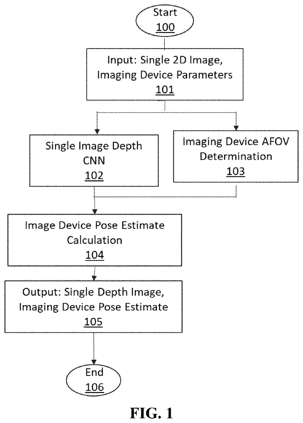
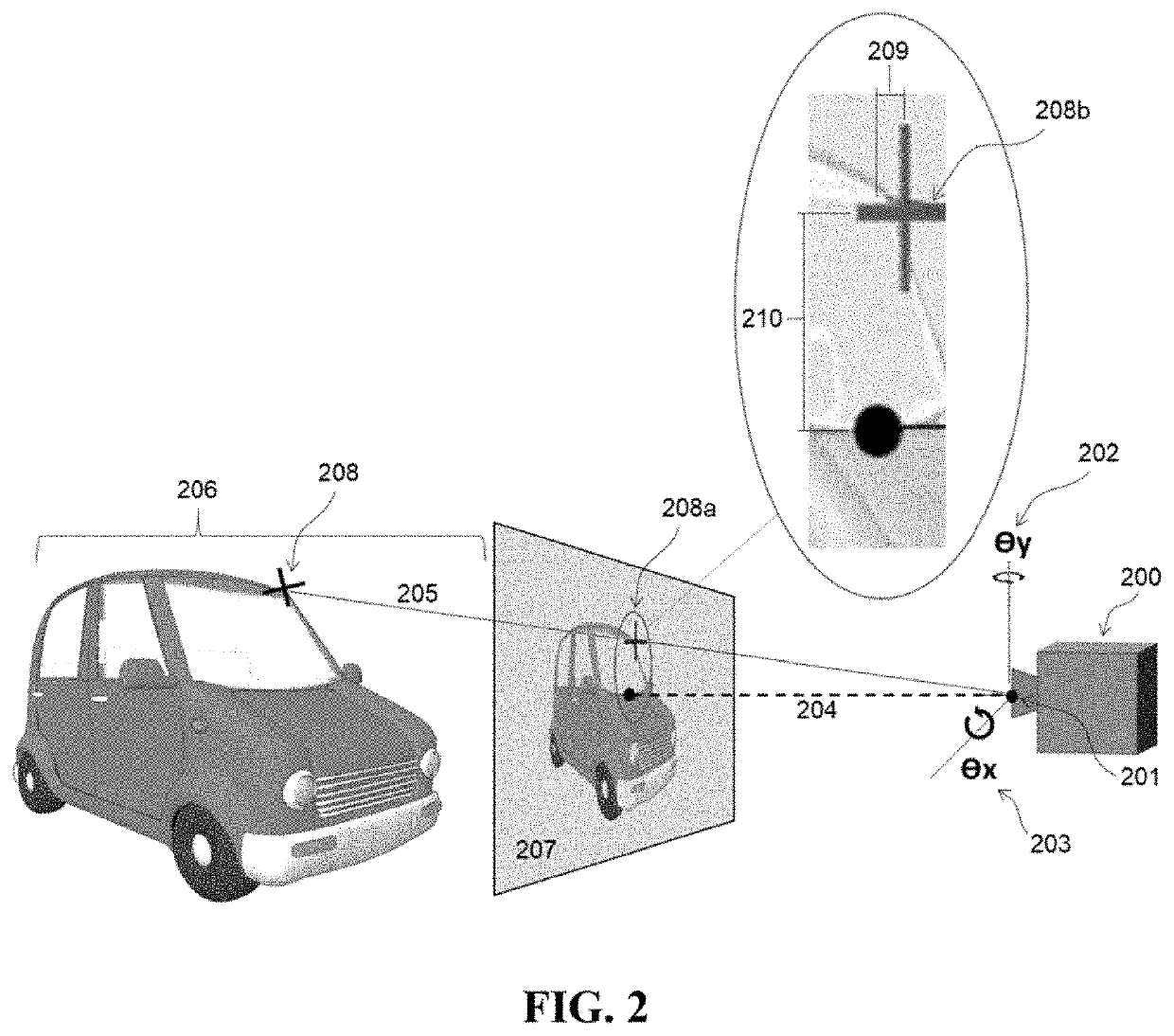
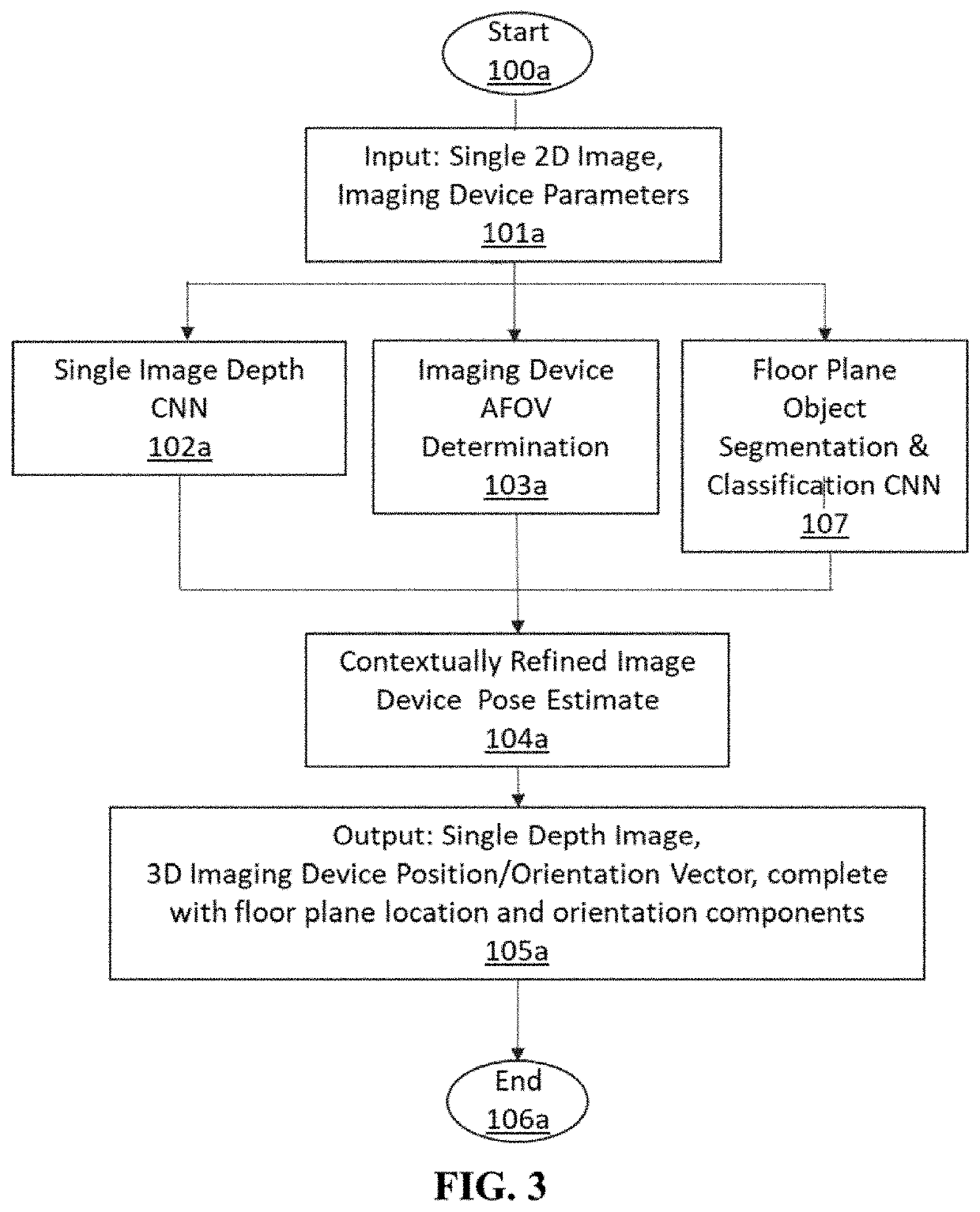
[0028]A method and exemplary implementation system for generating an accurate 3D pose estimate of a source image sensor relative to 3D objects in an observed scene, based on a 2D source image input, is described. Referring to the figures, like numerals indicate like or corresponding parts throughout several views. Many specific details are set forth in order to provide a thorough understanding of the embodiments described herein, but it is understood by those of ordinary skill in the art that the embodiments described herein may be practiced without these specific details. Further, in other instances, well-known optional features (i.e. methods, procedures and components) have not been described in detail so as not to obscure the embodiments described herein, but it is understood by those of ordinary skill in the art that such optional features may be practiced in conjunction with the disclosed invention. The description is not to be considered as limiting the scope of the embodiment...


PUM


Abstract

A method for deriving an image sensor's 3D pose estimate from a 2D scene image input includes at least one Machine Learning algorithm trained a priori to generate a 3D depth map estimate from the 2D image input, which is used in conjunction with physical attributes of the source imaging device to make an accurate estimate of the imaging device 3D location and orientation relative to the 3D content of the imaged scene. The system may optionally employ additional Machine Learning algorithms to recognize objects within the scene to further infer contextual information about the scene, such as the image sensor pose estimate relative to the floor plane or the gravity vector. The resultant refined imaging device localization data can be applied to static (picture) or dynamic (video), 2D or 3D images, and is useful in many applications, most specifically for the purposes of improving the realism and accuracy of primarily static, but also dynamic Augmented Reality (AR) applications.

Description

CROSS REFERENCE TO RELATED APPLICATIONS[0001]This application claims priority from U.S. Provisional Application No. 62 / 508,446 filed May 19, 2017, entitled “ARTIFICIAL NEURAL NETWORK BASED MODELING & LOCALIZATION SYSTEM.” The content of the aforementioned application is hereby expressly incorporated by reference into the present application in its entirety.FIELD OF THE INVENTION[0002]The invention relates generally to a method for localizing and globally orienting an imaging device (e.g. a camera) in an observed environment based on analysis conducted by a trainable automated system on at least one 2-Dimensional image of a scene within the subject environment.BACKGROUND OF THE INVENTION[0003]Augmented Reality (AR) is a mode of Human Computer Interaction in which virtual content is overlaid onto a user's visual perception of their local environment such that the virtual content appears to be physically present in a given scene. The overlay may occur on static images in an offline mod...

Claims


Application Information

Patent Timeline
Patent Type & Authority Patents(United States)
IPC IPC(8): G06T7/70G06N3/08G06T7/50G06N3/04G06T7/536G06T7/77
CPCG06T7/70G06N3/04G06N3/08G06T7/50G06T7/536G06T7/77G06T2207/20081G06T2207/20084G06T2207/30244
Inventor CLARK, TAYLORKEMENDO, ANDREWSHANKS, MARK
Owner MANOR FINANCIAL INC
Learn More