Eureka AIR delivers breakthrough ideas for toughest innovation challenges, trusted by R&D personnel around the world.

Method and apparatus for determination of phase distributions in magnetic resonance imaging

a magnetic resonance imaging and phase distribution technology, applied in the field of magnetic resonance imaging phase distribution determination, can solve the problems of weak spatial variation in signal phase, unavoidable strong spatial variation, and limited value range, and achieve the effect of quick and efficient determination of phase differences, quick and efficient determination, and fast and efficient determination

Active Publication Date: 2021-04-20
SIEMENS HEALTHCARE GMBH
View PDF6 Cites 0 Cited by
  • Summary
  • Abstract
  • Description
  • Claims
  • Application Information

AI Technical Summary

Benefits of technology

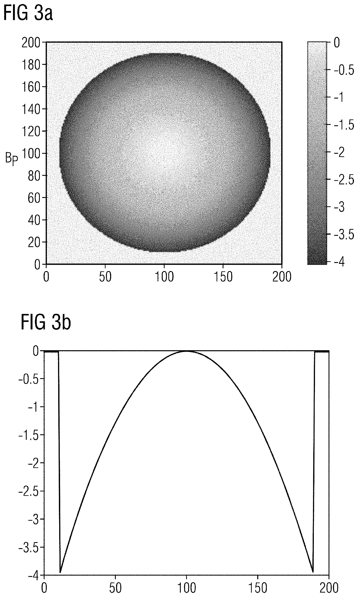
[0011]The method according to the invention utilizes knowledge of the spatial distribution of a basic magnetic field, in particular of rapidly spatially varying contributions of a known magnetic field distribution in an edge region of a region of interest and thus reduces the errors in the determination of phase distributions in the edge region. In particular, the method according to the invention reduces the spatial variation of a signal phase of measured MR data by separating a component of a priori known spatial variations in the signal phase. This generates a more benign spatial phase distribution, which is substantially induced by an object, which enables less error-susceptible determination of relative phase relationships in MR imaging methods based on phase information. Hence, this results in improved robustness and precision of MR imaging methods based on phase information, in particular in the edge of image recording regions.
[0016]The combination of the first measured phase distribution and the at least one second phase value can be a determination of a phase-difference distribution. The phase-difference distribution is a spatial assignment of phase differences of individual voxels in the region of interest. This enables a quick and efficient determination of phase differences in MR imaging methods for the generation of MR images.
[0017]The determination of the first measured phase distribution can include measurement of a phase distribution of the region of interest, i.e. a spatial distribution of phase values, or in other words a spatial assignment of phase values to individual points in the region of interest, after a first evolution period. Herein, the phase values of the phase distribution are based on the known magnetic field distribution in the region of interest. The determination of a phase distribution based on a magnetic field distribution in the region of interest following a first evolution period is required in numerous MR imaging methods for the generation of MR images and hence phase combination can be performed quickly and efficiently.
[0018]The provision of at least one second phase value can be a provision of a second measured phase distribution of the region of interest. Furthermore, the provision of the second measured phase distribution can be a measurement of a phase distribution of an MR image after a second evolution period that is different from the first evolution period. The provision of at least one second phase value can be a definition of a global phase value of the region of interest. Hence, a phase distribution can be determined quickly and efficiently in many MR imaging methods for the generation of MR images.

Problems solved by technology

A problem with such methods is due to the limited value range of the phase information ascertained from measured variables.
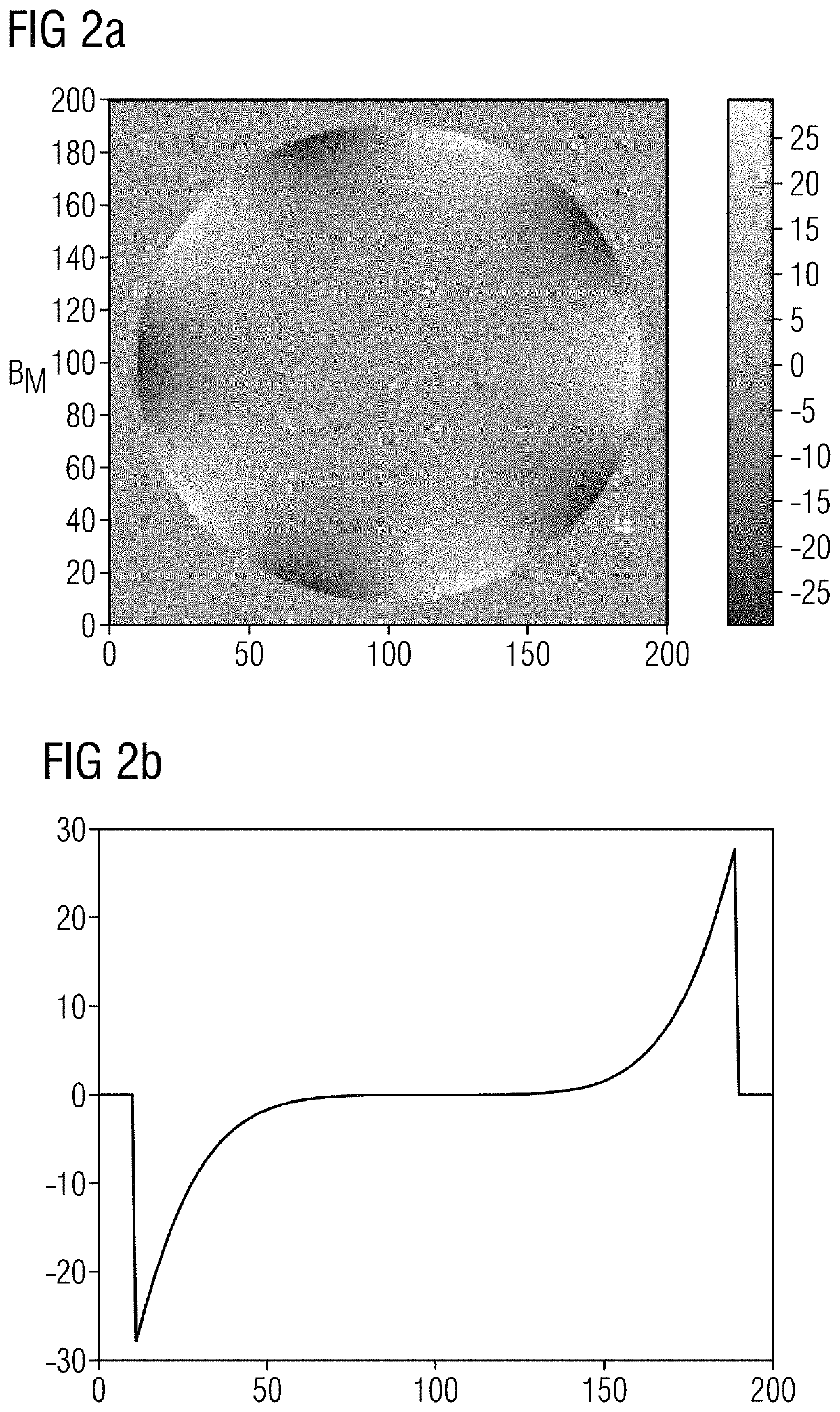
Due to the design of the basic field magnet, strong spatial variations in the signal phase are unavoidable in particular at the edge of the image recording region.
In these regions, errors frequently occur in the determination of the actual phase difference which consequently result in erroneous or imprecise representations.
However, in the edge region of the magnet, the component of the signal phase induced by inhomogeneities of the magnetic field can vary very rapidly thus resulting in the determination of erroneous additional phases.
The successive approach used causes these errors to be propagated over large image regions.
However, in the edge region of the magnet, the components of the signal phase induced by inhomogeneities in the magnetic field vary very rapidly and are hence erroneously assigned to the useful signal.

Method used


Image

  • Method and apparatus for determination of phase distributions in magnetic resonance imaging
  • Method and apparatus for determination of phase distributions in magnetic resonance imaging
  • Method and apparatus for determination of phase distributions in magnetic resonance imaging

Examples


Embodiment Construction

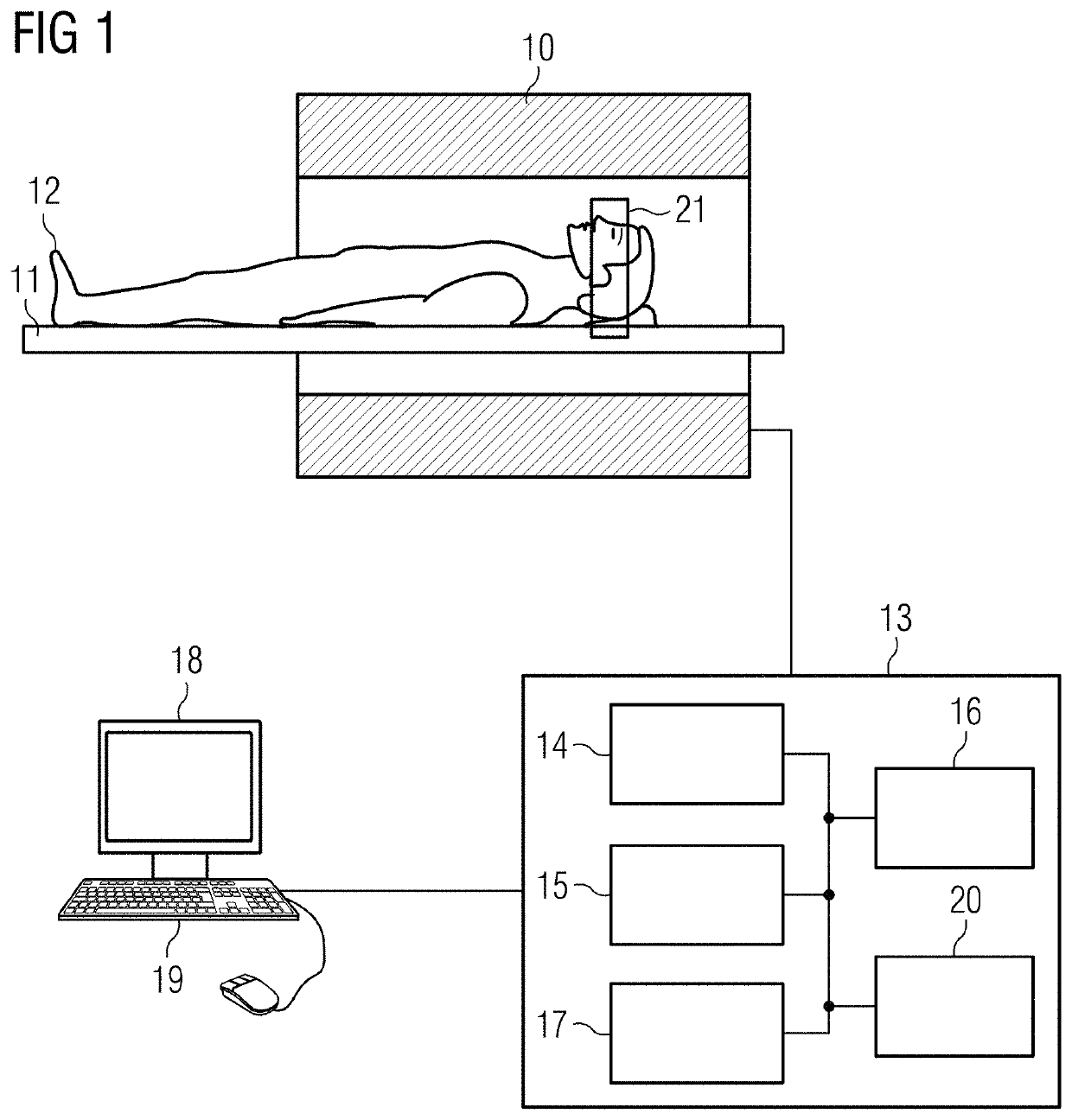
[0037]FIG. 1 schematically shows an MR system with which the method for the determination of a phase distribution of a region of interest 21 according to the invention can be carried out.

[0038]A person 12 under examination, or more generally an object under examination, is in moved into the tunnel of the system, wherein a region of interest 21 is examined by the MR system. The magnetic resonance system has a scanner 10 with a basic field magnet that generates a basic magnetic field B0. The person 12 under examination, arranged on a bed 11, is moved into the center of the scanner 10 in order to record spatially encoded magnetic signals from the region of interest 21. Radiation of radio-frequency (RF) pulse sequences and switching of magnetic field gradients causes certain nuclear spins in the person 12 to be deflected from the magnetization generated by the basic field B0, out of the equilibrium position. Currents induced in RF reception coils, as the excited spins return to the equi...


PUM


Abstract

In a method and apparatus for determination of phase distributions in MR imaging, a measured phase distribution of the region of interest is combined with at least one second phase value to form a combination-phase distribution, wherein the phase values of the combination-phase distribution are restricted to a defined presentation interval. A correction-phase distribution is generated, based on a known magnetic field distribution in the region of interest. The phase values thereof are not restricted to the defined presentation interval. A corrected combination-phase distribution is generated using the correction-phase distribution and the combination-phase distribution, in which the phase values are restricted to the defined presentation interval. An absolute combination-phase distribution is generated from the corrected combination-phase distribution, in which the phase values are not restricted to the defined presentation interval.

Description

BACKGROUND OF THE INVENTIONField of the Invention[0001]The present invention concerns the determination of phase distributions in magnetic resonance (MR) imaging and in particular a method for the determination of a phase distribution of a region of interest, which is determined in order to generate an MR image of the region of interest by operation of an MR system.Description of the Prior Art[0002]A number of MR imaging methods use—sometimes in addition to the amplitude—the phase of the MR signal as basic information. Such MR imaging methods include, for example, B0 mapping, which includes spatial representation of a variation of the B0 field amplitude, susceptibility-weighted imaging (SWI), which is based on image weighting taking into account tissue-induced variations in the local B0 field amplitude (for example, due to the presence of hemoglobin in the event of hemorrhage), quantitative susceptibility mapping (QSM), which includes quantitative spatial determination and represent...

Claims


Application Information

Patent Timeline
Patent Type & Authority Patents(United States)
IPC IPC(8): G01R33/24G01R33/565A61B5/055G01R33/48G01R33/563A61B5/00G01R33/3415
CPCG01R33/246A61B5/055G01R33/4804G01R33/56316G01R33/56563A61B5/0037G01R33/243G01R33/3415G01R33/56536
Inventor FEIWEIER, THORSTENNIEDERLOEHNER, DANIEL
Owner SIEMENS HEALTHCARE GMBH
Why Eureka
Eureka Blog
Learn More