Wireless inductive power transfer

a technology of inductive power transfer and wireless, which is applied in the direction of inductance, transformer, transportation and packaging, etc., can solve the problems of voltages being induced that exceed the level considered unsuitable for the circuitry of the power receiver, over-voltage conditions at the power receiver, etc., and achieves quick increase in coupling and efficient power control

Active Publication Date: 2021-04-20
KONINKLJIJKE PHILIPS NV
View PDF10 Cites 0 Cited by
  • Summary
  • Abstract
  • Description
  • Claims
  • Application Information

AI Technical Summary

Benefits of technology

[0015]The invention may provide improved power transfer in many scenarios. In particular, improved power control may be achieved. In many embodiments, the approach may provide an improved reliability and may in particular provide improved protection against over-voltage conditions occurring at the power receiver as a result of fast changes in the coupling factor resulting e.g. from movement of the power receiver relative to the power transmitter.
[0064]This may provide a particularly efficient operation in many embodiments. For example, it may in many embodiments reduce the number of messages that need to be communicated (and thus the processing resource required to process and react to messages).

Problems solved by technology

In particular, the inventors have realized that many current power transfer systems (such as ones following the Qi specifications) include a power control loop which may in some scenarios result in over-voltage conditions occurring at power receivers due to sudden changes in the coupling between the power transmitter and power receiver.
In particular, it has been found that many existing power control approaches when extended to higher power levels may, when a quick change in the coupling occurs, result in voltages being induced that exceed levels which are considered unsuitable for circuitry of the power receiver.

Method used


Image

  • Wireless inductive power transfer
  • Wireless inductive power transfer
  • Wireless inductive power transfer

Examples


Embodiment Construction

[0082]The following description focuses on embodiments of the invention applicable to a wireless power transfer system utilizing a power transfer approach such as known from the Qi specification. However, it will be appreciated that the invention is not limited to this application but may be applied to many other wireless power transfer systems.

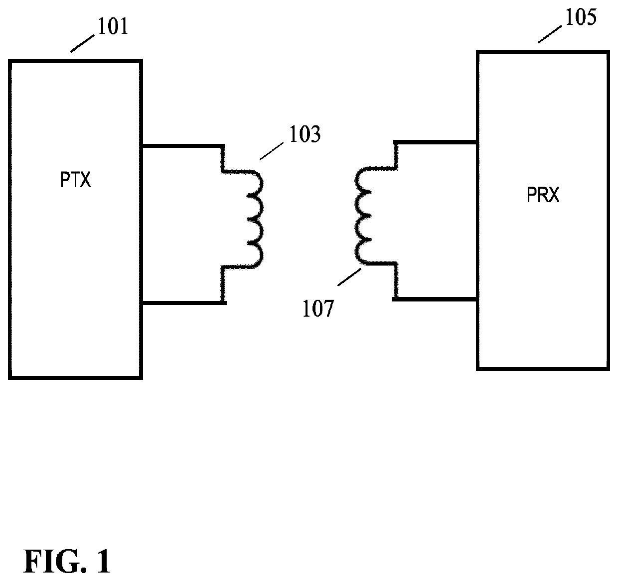
[0083]FIG. 1 illustrates an example of a power transfer system in accordance with some embodiments of the invention. The power transfer system comprises a power transmitter 101 which includes (or is coupled to) a transmitter coil / inductor 103. The system further comprises a power receiver 105 which includes (or is coupled to) a receiver coil / inductor 107.

[0084]The system provides a wireless inductive power transfer from the power transmitter 101 to the receiver 105. Specifically, the power transmitter 101 generates a wireless inductive power transfer signal (also referred to as a power transfer signal, power transfer signal or an inductive po...


PUM

PropertyMeasurementUnit
frequencyaaaaaaaaaa
frequencyaaaaaaaaaa
frequencyaaaaaaaaaa

Abstract

A power transmitter (101) of a wireless power transfer system comprises a resonance including a transmitter coil (103) for generating a power transfer signal for wirelessly transferring power to a power receiver (105). Further, a driver (1303) generates a drive signal for the resonance circuit (201) and a message receiver (1305) is arranged to receive messages from the power receiver (105). A power loop controller (1307) implements a power control loop by adapting the power of the drive signal in response to power control messages received from the power receiver (105). However, the regulation is subject to a constraint of at least one of a current or voltage of the resonance circuit and a power of the drive signal being below a maximum limit. Further, the power transmitter (101) comprises an adapter (1309) which adapts the maximum limit in response to a load indication indicative of a loading of the power transfer signal by the power receiver (105).

Description

CROSS-REFERENCE TO PRIOR APPLICATIONS[0001]This application is the U.S. National Phase application under 35 U.S.C. § 371 of International Application No. PCT / EP2017 / 050169, filed on 5 Jan. 2017, which claims the benefit of European Patent Application No. 16151007.8, filed on 13 Jan. 2016. These applications are hereby incorporated by reference herein.FIELD OF THE INVENTION[0002]The invention relates to inductive power transfer and in particular, but not exclusively, to a power transmitter providing inductive power transfer using elements compatible with the Qi Specifications for wireless power transfer systems.BACKGROUND OF THE INVENTION[0003]Most present day systems require a dedicated electrical contact in order to be powered from an external power supply. However, this tends to be impractical and requires the user to physically insert connectors or otherwise establish a physical electrical contact. Typically, power requirements also differ significantly, and currently most device...

Claims


Application Information

Patent Timeline
Patent Type & Authority Patents(United States)
IPC IPC(8): H01F38/00H02J50/12H02J50/80H01F27/28H02J7/02
CPCH02J50/12H01F27/28H02J7/025H02J50/80
Inventor STARING, ANTONIUS ADRIAAN MARIAVAN WAGENINGEN, ANDRIES
Owner KONINKLJIJKE PHILIPS NV
Why Eureka
Try Eureka