Radome for vehicles and method for manufacturing said radome

a technology for radome and vehicles, which is applied in the direction of antennas, de-icing/drying out arrangements, and reradiation, etc., can solve the problems of difficult integration of heating capability into decorative radome, increased driving danger, and snow a clear danger to the functionality of radar

Active Publication Date: 2021-05-11
ZANINI AUTO GRUP
View PDF16 Cites 2 Cited by
  • Summary
  • Abstract
  • Description
  • Claims
  • Application Information

AI Technical Summary

Benefits of technology

[0018]With the radome according to the present invention it is possible to solve said drawbacks, providing other advantages that are described below.
[0035]The invention discloses a radome with a heating function and an outstanding appearance. Furthermore, the invention provides a simplified and robust process to connect the heating element of the radome to an electrical connector, which is typically located on the radome innermost surface, facing the vehicle engine.

Problems solved by technology

This is especially important in adverse weather conditions, when driving becomes more dangerous due to loss of visibility, road ground conditions and other.
Obviously, water, ice and snow represent a clear danger for the functionality of the radar, as they block radar waves and can be deposited over the radome surface.
Integrating a heating capability in a decorative radome is a difficult task given the complexity of the design, the different materials employed, and the decoration technologies required to faithfully reproduce a brand logo.
This document does not provide a solution for the manufacturing of the radome, only a concept that would need to be produced.
Main limitation of this invention comes from the fact of employing circuit tracks, as the performance of a radome using this technology is significantly worse than using conductive wires.
The issue is distance between conductor paths and the front surface, where ice or snow will deposit and will need to be removed.
Here again, the issue is distance between conductive elements and the front surface, where ice or snow will deposit and will need to be removed.
Although this solution may allow placing the foil on the outermost radome surface, thus optimizing heating transfer and efficiency, it lacks protection in the contact area.
Therefore, metals at that point are subject to corrosion and degradations over time due to their exposure to the environment.
It has been shown the issues affecting design and manufacturing of heatable radome solutions.

Method used


Image

  • Radome for vehicles and method for manufacturing said radome

Examples


first embodiment

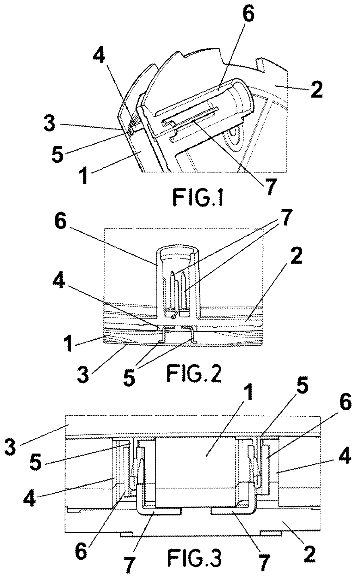
[0048]FIGS. 1 and 2 are section views showing the radome for vehicles according to the present invention; and

second embodiment

[0049]FIG. 3 is a section view showing the radome for vehicles according to the present invention.

DESCRIPTION OF PREFERRED EMBODIMENTS

[0050]A first embodiment of the radome for vehicles according to the present invention is shown in FIGS. 1 and 2.

[0051]The radome comprises a frontal layer 1 and a rear layer 2 that are assembled to each other. Both layers are made form a thermoplastic material.

[0052]According to the present invention a heating element 3 is placed on the frontal surface of the frontal layer 1, i.e. in the external surface of the radome.

[0053]According to a preferred embodiment, this heating element 3 is a foil provided with a plurality of conductive wires, preferably embedded in the foil.

[0054]The heating element 3 comprises a recess 4 for housing a conductive element 5, that in this embodiment is a pad.

[0055]The rear layer 2 comprises a case 6 for a connector (not shown in the drawings) that is connected directly to the electric source of the vehicle. And this case 6...


PUM


Abstract

The radome for vehicles includes a frontal layer (1) and a rear layer (2), both made from thermoplastic material, and it also includes a heating element (3) placed on the frontal layer (1), on its face opposed to the rear layer (2). The method for manufacturing the radome includes forming the frontal layer (1) with the heating element (3) placed on a face of the frontal layer (1); placing the conductive element(s) (5) in the heating element (3) ; forming the rear layer (2); assembling the frontal and rear layers (1, 2), so that the heating element (3) is on the face of the frontal layer (1) opposite to the rear layer (2). Some embodiments provide a radome with a heating function and an outstanding appearance.

Description

CROSS-REFERENCE TO RELATED APPLICATIONS[0001]The present application claims the benefit of and priority to European Patent Application No. 18382634.6, filed on Aug. 30, 2018, the entire disclosure of which is incorporated by reference as if set forth in its entirety herein.[0002]The present invention refers to a radome for vehicles, such as a decorative radome used as an emblem which possesses a metallic image, especially for radomes disposed in front of a radar in the front grill of a vehicle, integrating heating capability. The present invention also refers to a method for manufacturing said radome.BACKGROUND OF THE INVENTION[0003]Vehicles with sensors able to sense their surroundings are the key enablers to decrease of road fatalities. Through sensors, driver assistance functions are implemented, minimizing risks and increasing the probability of avoiding collisions.[0004]Vehicles are designed to offer an aesthetically pleasant impression. Therefore, sensors must be integrated wi...

Claims


Application Information

Patent Timeline
Patent Type & Authority Patents(United States)
IPC IPC(8): H01Q1/02H01Q1/32H01Q1/42G01S13/931G01S7/40
CPCH01Q1/02H01Q1/3233H01Q1/3283H01Q1/422H01Q1/425G01S13/931G01S2007/4047G01S2013/93271H01Q1/42G01S7/02G01S7/027H01Q1/3216G01S7/4043G01S7/4047
Inventor MASCARÓ HEREZA, MARÇALCASANOVAS CEJUELA, MIQUELSANAHUJA CLOT, JOSÉBOVER BALDERICH, MARCMAYER PUJADAS, AUGUSTO
Owner ZANINI AUTO GRUP
Why Eureka
Try Eureka