System and method for displaying anatomy and devices on a movable display

a technology of anatomy and movable display, applied in the field of diagnosis and treatment of disorders, can solve problems such as difficult viewing of the screen, and achieve the effects of easy navigation, quick selection of access points, and light angular bias

Active Publication Date: 2021-06-01
AURIS HEALTH INC
View PDF680 Cites 284 Cited by
  • Summary
  • Abstract
  • Description
  • Claims
  • Application Information

AI Technical Summary

Benefits of technology

[0016]Embodiments of the invention possess inventive design elements that provide excellent user ergonomics and increase the functional anatomical workspace of the virtual window surgical system. Coupling the position and orientation of the display to the image allows the image to remain aligned to the patient for various positions and orientations of the display. To improve the ergonomics and workspace of the system, the knowledge of the general position of the user relative to the patient is leveraged to slightly bias the image position to an optimized position. For example, if the user is on the left side of the patient, the image may be angled fifteen degrees away from the user so that when the display is angled fifteen degrees toward the user, the image will appear flat relative to the patient. Practice has shown that the intuitive benefits to the user of an aligned image may still be captured when small angular offsets are in place, with offsets of 30 degrees being the well-tolerated limit in many procedures. The system uses the knowledge of the user's position to bias the display toward more comfortable positions. The knowledge of the user's position may be input to the system by the user, inferred by the system using the position of the display, or sensed by the system using position or contact devices on the system. To further increase the workspace of the system, this invention allows for decoupling the relationship to reposition the display independently of the image. For instance, an aligned display may interfere with other equipment during some portion of the procedure and it may be desirable to reposition the display slightly to relieve the interference. Additionally this invention allows for a scaled coupling for improved ergonomics. For instance, moving the display with a unity ratio may cause the display to interfere with other equipment during some portion of the procedure or may make the screen difficult to view. Up to a 1.5:1 scale may be used to optimize the ergonomics of the system while maintaining the visual coherency between the patient and the image. It should be noted that the display may be repositioned along multiple axes and in multiple directions and that the scaling may be different for different axes and directions. For example, the scaling may be unity in the translational axes and 1.3:1 in the rotational axes.
[0024]Elements of both embodiments may be combined to display preoperative and intra-operative anatomical images within the same procedure. In both embodiments, the invention provides a virtual window into the patient where the physician may view the anatomy and navigate the surgical device in substantial alignment with the patient. For example, sensored endoscope may be shown relative to the aligned anatomical image. An anatomical target may be chosen and marked on the image. As sensored medical devices are moved to different potential access points on the body, the ability to reach the anatomical target may be shown by projecting the path of the device to the target and presenting a positive indication when the path to the anatomical target is uninterrupted. Similar real-time updates may be used to assist in quickly choosing access points for minimally invasive devices by showing whether adjacent medical devices will collide with each other, external anatomy, or internal anatomy as different potential access points on the body are selected by moving the medical device to those access points.

Problems solved by technology

For instance, moving the display with a unity ratio may cause the display to interfere with other equipment during some portion of the procedure or may make the screen difficult to view.

Method used


Image

  • System and method for displaying anatomy and devices on a movable display
  • System and method for displaying anatomy and devices on a movable display
  • System and method for displaying anatomy and devices on a movable display

Examples


Embodiment Construction

[0031]While preferred embodiments of the present invention have been shown and described herein, it will be obvious to those skilled in the art that such embodiments are provided by way of example only. Numerous variations, changes, and substitutions will now occur to those skilled in the art without departing from the invention. It should be understood that various alternatives to the embodiments of the invention described herein may be employed in practicing the invention. It is intended that the following claims define the scope of the invention and that methods and structures within the scope of these claims and their equivalents be covered thereby.

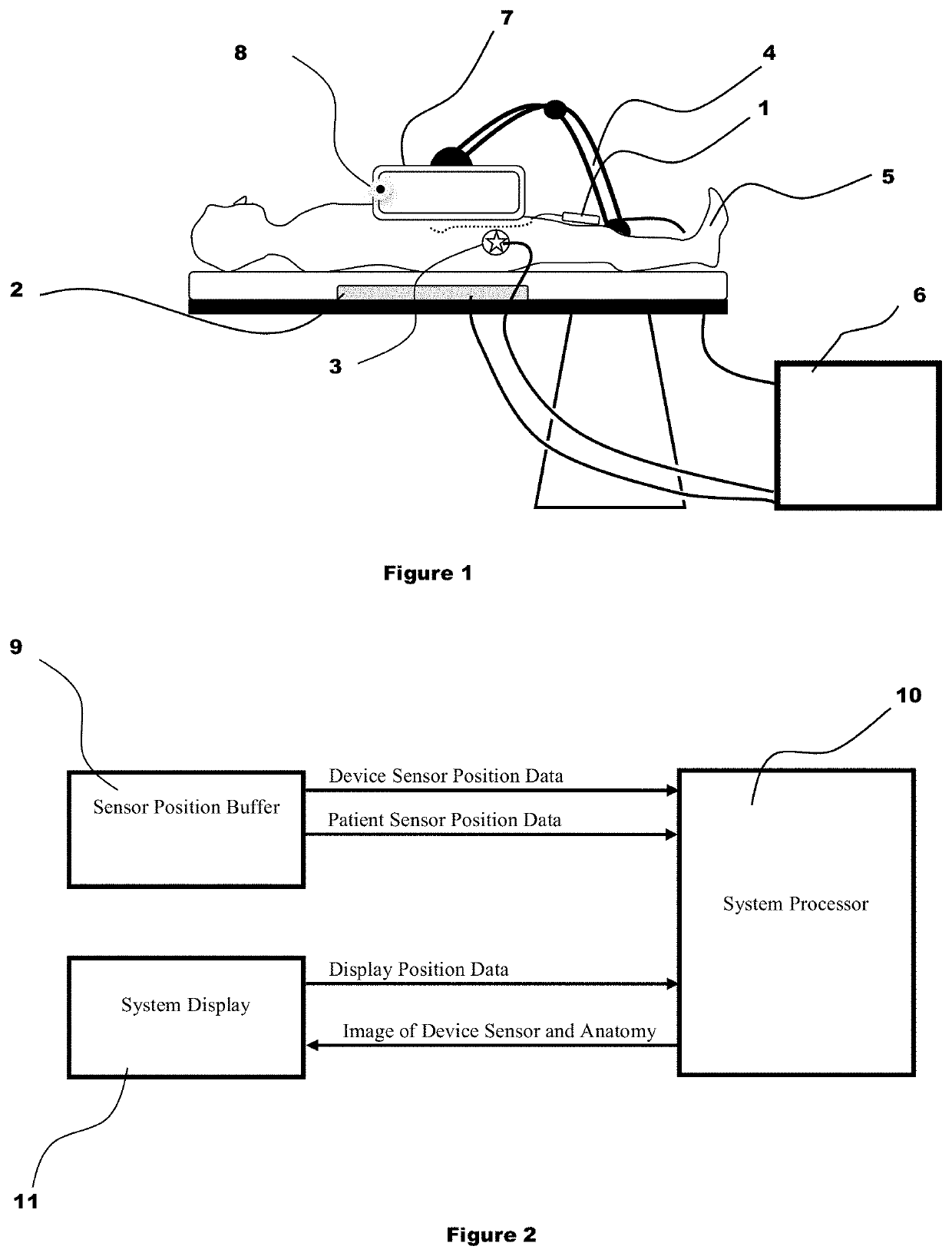
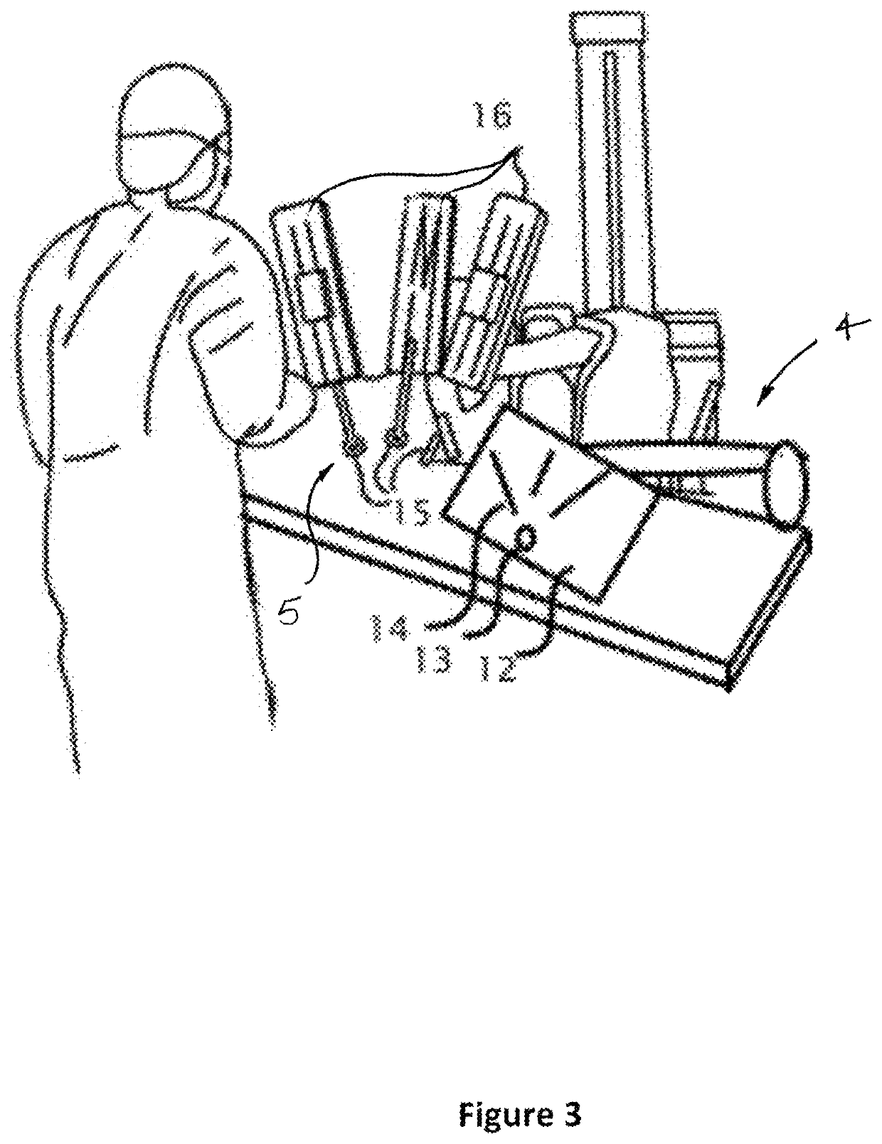
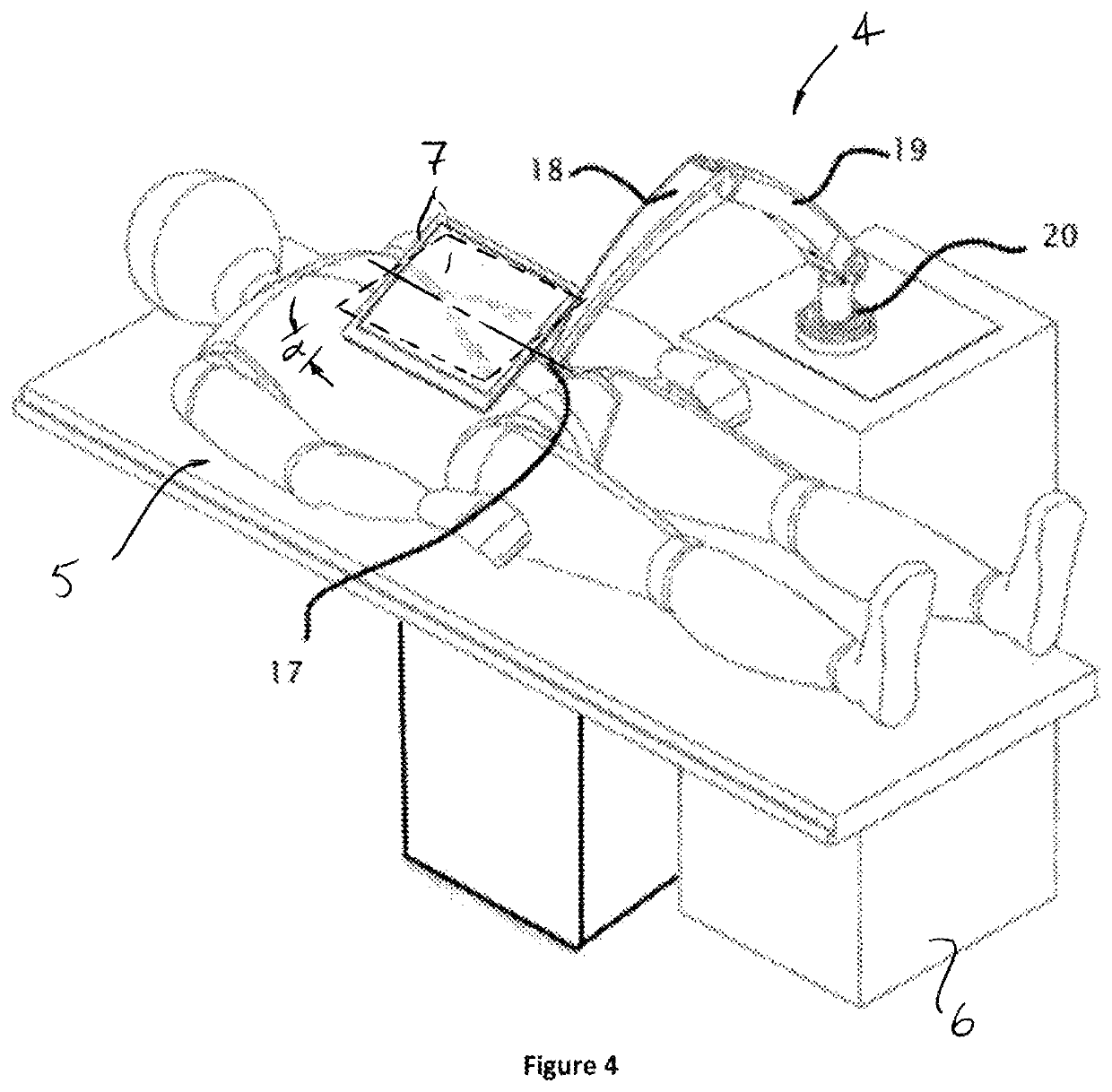
[0032]FIGS. 1-2 describe an embodiment for navigating a minimally invasive medical device within the patient using an acquired three-dimensional anatomical image shown in a display 7 that is substantially aligned to the patient anatomy. A sterile cover may be used to separate the display from the sterile operating field and the steril...


PUM


Abstract

An image display system is provided comprised of a virtual window system that creates a visual coherency between the patient's anatomical images and the actual patient by aligning the image on the display to the patient and then presenting the image to the user in a way that feels as if the user is looking directly into the patient through the display. The image shown within the image display system is dependent upon the position of the image display apparatus and the position of the user so that the display orientation of the image may be biased slightly toward the user to improve ergonomics and usability.

Description

CROSS-REFERENCE[0001]1. This application claims the benefit of U.S. Provisional Application No. 61 / 829,078 filed May 30, 2013.BACKGROUND OF THE INVENTION1. Field of the Invention[0002]The invention relates generally to the diagnosis and treatment of disorders using minimally invasive techniques. In many minimally invasive procedures very small devices are manipulated within the patient's body under visualization from a live imaging source like ultrasound, fluoroscopy, or endoscopy. Live imaging in a minimally invasive procedure may be supplemented or replaced by displaying the position of a sensored medical device within a stored image of the patient anatomy.[0003]Many minimally invasive procedures are conducted in expensive settings by specialized physicians. Often small, percutaneous medical devices are visualized during the procedure by using live fluoroscopic or ultrasonic imaging. While the live imaging provides a real-time image of anatomy, it has many drawbacks:[0004]Time spe...

Claims


Application Information

Patent Timeline
Patent Type & Authority Patents(United States)
IPC IPC(8): A61B34/10A61B34/20A61B34/30A61B5/06A61B5/00A61B90/00A61B6/00A61B8/08A61B5/055
CPCA61B5/062A61B5/7425A61B90/37A61B5/055A61B5/7445A61B6/487A61B8/0833A61B2034/2051G16H40/63G16H20/40
Inventor WALLACE, DANIELSTAHLER, GREGORYGROGAN, AARON
Owner AURIS HEALTH INC
Why Eureka
Try Eureka