Scanner nozzle array, showerhead assembly and method

a technology of scanning nozzles and showerheads, applied in the direction of spray nozzles, movable spraying apparatus, spraying apparatus, etc., can solve the problems of unsatisfactory spray pattern of standard jet-type shower heads, difficulty in manufacturing prior fluidic showerheads, and inability to provide pleasing spray patterns, etc., to improve the performance of various types of fluidic sprayers, improve the performance of fluidic sprayers, and reduce energy consumption

Active Publication Date: 2021-06-29
DLHBOWLES INC
View PDF23 Cites 0 Cited by
  • Summary
  • Abstract
  • Description
  • Claims
  • Application Information

AI Technical Summary

Benefits of technology

[0015]In striving to improve the performance of various types of fluidic sprayers, applicants have discovered that there are significant opportunities to create and introduce new enclosures for these fluidic oscillators that appreciably improve their performance. Accordingly, it is an object of the present invention to provide improved enclosures and fluidic oscillating sprays for shower head assemblies that can provide reduced energy consumption, while still yielding sprays that provide desired tactile sensations as they impact upon the skin of a user, as well as providing better directional control of the spray to permit control of the location of the areas being wetted by the sprays from such assemblies.
[0016]Another object of the present invention to provide enclosures for fluidic spray assemblies that can make “less water” feel like “more water”, as by providing low flow rate sprays that provide the same tactile sensations as higher flow rates in non-fluidic sprays as they impact upon the skin of a user.
[0017]Still another object of the present invention is the provision of scanner spray assemblies having multiple outlet nozzles, with each nozzle having a preselected spray characteristic to produce improved showerhead patterns.

Problems solved by technology

Standard jet-type shower heads do not provide pleasing spray pattern, uniform droplet size, uniform droplet velocity, and temperature uniformity at very low flow rates (e.g., 2 gpm or less) for showering.
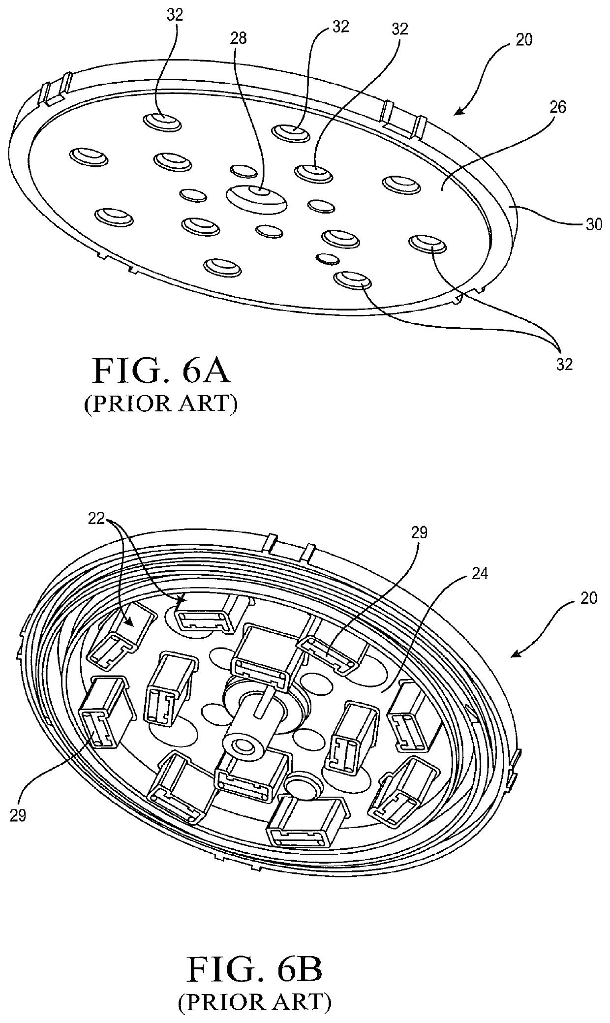
Most fluidic-equipped showerheads have very few spray generating openings and are, therefore, initially considered inferior by un-knowing consumers at stores where they cannot spray the showerhead before purchasing.
Prior fluidic showerheads are also tricky to manufacture because of the difficulty in sealing of the fluidic passages.
Prior fluidic showerheads also tend to be more expensive than conventional jet showers because of the number of component fluidics.
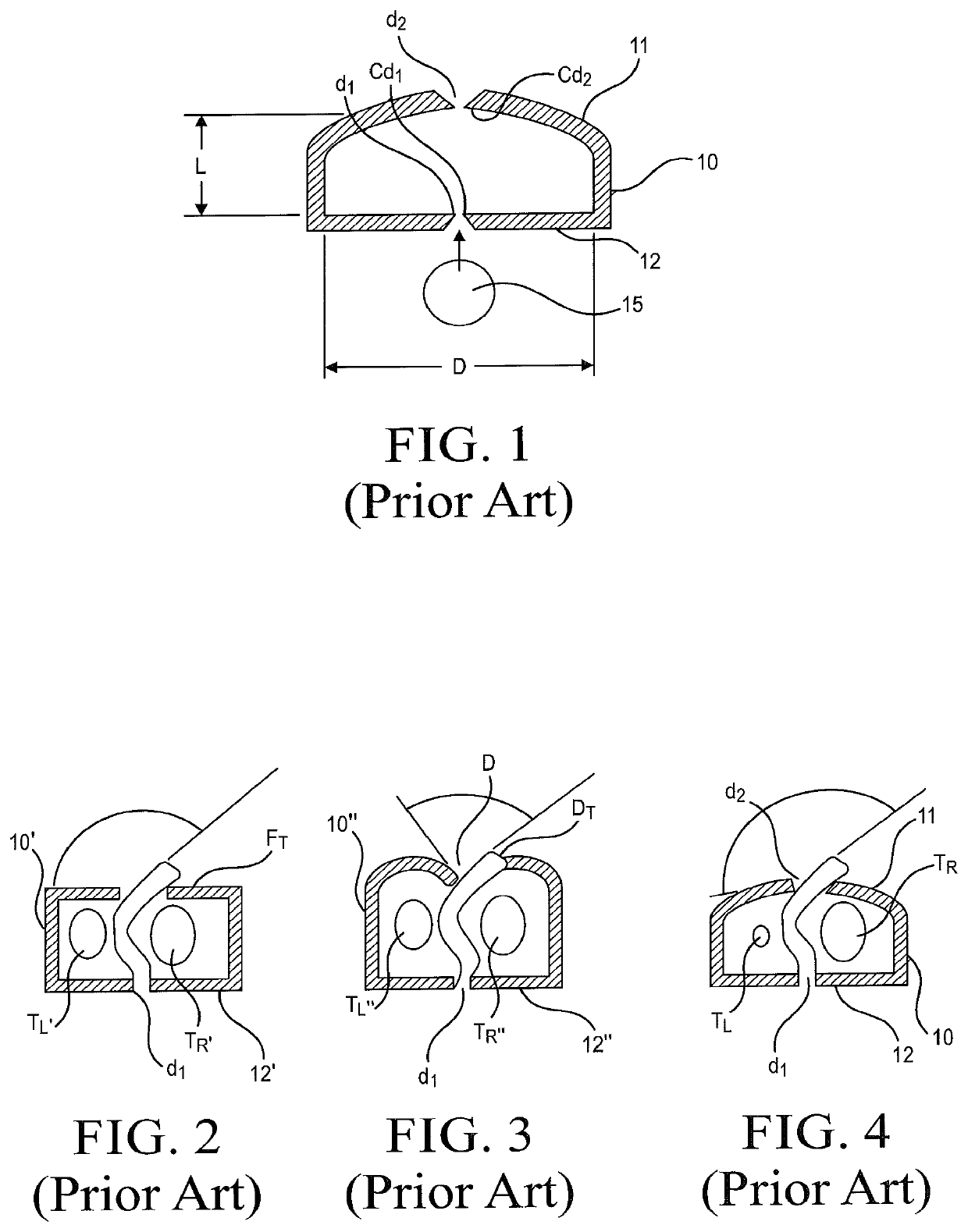
Despite much prior art relating to the development of fluidic circuits, the nature of the housings or enclosures that surround fluidic oscillators have not changed much over the years.

Method used


Image

  • Scanner nozzle array, showerhead assembly and method
  • Scanner nozzle array, showerhead assembly and method
  • Scanner nozzle array, showerhead assembly and method

Examples


first embodiment

[0084]Turning now to a more detailed description of the present invention, reference is made to FIGS. 7-13, which illustrate at 50 a fluidic scanning spray device which may be in the form of a hand-held body sprayer or shower, a fixedly or movably mounted showerhead, or the like, and which for convenience will be referred to herein as a scanner showerhead which incorporates a multiplicity of fluidic oscillators. The scanner showerhead 50 preferably is of a molded plastic material and includes a two-piece housing 52 having a rear (or top as viewed in FIG. 7) housing component 54 and a front plate (or bottom, as viewed in the Figure) housing component 56 mated at an interface 58 to form an enclosed plenum which encloses the fluidic oscillator elements of the invention, as will be described. As illustrated, the top housing component 54 incorporates a fluid inlet 60 for connection to a source of fluid under pressure, such as a conventional sprayer or shower supply fixture or hose (not s...

second embodiment

[0090]The simplicity of the scanner geometry—an essentially spherical interaction region with opposed, but selectively offset, inlet (power nozzle) and outlet (throat)—allows for simplified construction of scanner fluidic arrays. As illustrated in the embodiment of FIGS. 7-9 and in the related second embodiment of the invention illustrated in FIGS. 10-15, such simplified construction is accomplished by molding the scanner throats and the downstream half of the interaction regions in one piece of the showerhead. In this scenario, as discussed above, the inserts containing the power nozzle and the upper, or upstream half of the interaction region are molded individually for each fluidic so that the component count for the fluidics device is equal to the number of fluidics plus one. This is more than in a prior fluidic shower, but the components are much simpler to design, mold, and assemble.

[0091]In the embodiment of FIGS. 10-17, which are directed to a second embodiment 198 of the pr...

fourth embodiment

[0097]FIGS. 21-25 illustrate at 400 the scanner sprayer of the present invention incorporating multiple fluidic oscillators wherein downstream (or front) halves of the oscillator interaction regions, including outlet apertures and throats, are all molded in one piece of the sprayer and upstream (or rear) halves of the oscillator including power nozzles and upstream halves of the interaction regions are molded in one other piece of the sprayer to simplify its manufacture and assembly. In this embodiment, the scanner sprayer 400, which is illustrated as a showerhead having multiple spray outlet streams, includes a rear (or upper as viewed in FIGS. 21 and 22) cup-shaped housing member 402 having a top wall 404 and a forwardly (downwardly as viewed in FIGS. 21 and 22) extending, generally cylindrical side wall 406 having an inward peripheral shoulder407. Centrally located in the top wall 402 is an upstanding fluid inlet fixture 408 having a cylindrical side wall 410 carrying external th...


PUM


Abstract

A new scanner fluidic oscillator is used in an economically manufactured fluidic showerhead or nozzle assembly 50, 198, 250, 400 which aims oscillating sprays from multiple scanner fluidics to spread water uniformly over a preselected coverage area. The scanner fluidics and showerhead of the present invention provide a pleasing spray pattern, droplet size, droplet velocity, and temperature uniformity at very low flow rates (i.e., 2 gpm or less) for showering. The scanner fluidics are provided in a plurality of distinct configurations for generating individually tailored scanning sprays having a selected scanning spray characteristics. The showerhead's front plate (e.g., 56, 200, 270, 454) is configured to support and aim the fluidic oscillators, optionally with indexing slots 802 configured to receive corresponding angular indexing tabs 800 on the fluidic oscillator inserts to orient and aim the spray from each fluidic oscillator (e.g., 172, 220,282, 530).

Description

REFERENCE TO RELATED APPLICATIONS[0001]This application is a 35 U.S.C. 371 national stage filing and claims priority to and the benefit of International Application No PCT / US2016 / 063608 filed on Nov. 23, 2016, which claims the priority benefit of U.S. provisional patent application No. 62 / 258,991, filed on Nov. 23, 2015, and entitled “SCANNER NOZZLE ARRAY AND SHOWERHEAD ASSEMBLY”. This application is also related to commonly owned U.S. Pat. Nos. 6,938,835, 6,948,244, 7,111,800, 7,677,480, and 8,205,812, which cover a prior embodiment of the commonly-owned scanner fluidic oscillator, multiple fluidic enclosures, and methods of integrating fluidic geometry (exit geometry) into the housing of a fluidic device. The entire disclosures of all of the foregoing applications and patents are hereby incorporated herein by reference.BACKGROUNDField of the Invention[0002]This invention relates to fluid handling processes and apparatus. More particularly, this invention relates to new methods and...

Claims


Application Information

Patent Timeline
Patent Type & Authority Patents(United States)
IPC IPC(8): B05B3/16B05B1/18
CPCB05B3/16B05B1/18B05B1/185
Inventor RUSSELL, GREGORY A.CROCKETT, STEVE
Owner DLHBOWLES INC
Why Eureka
Try Eureka