
Liquid crystal panel and manufacturing method thereof

a technology of liquid crystal panels and manufacturing methods, applied in non-linear optics, instruments, optics, etc., can solve the problem of reducing the screen-to-body ratio of products, and achieve the effect of reducing the problem of excessive frame width

Active Publication Date: 2021-06-29
AU OPTRONICS CORP
View PDF25 Cites 0 Cited by
  • Summary
  • Abstract
  • Description
  • Claims
  • Application Information

AI Technical Summary

Benefits of technology

[0004]The invention provides a liquid crystal panel, which alleviates a problem of excessive width of a frame.
[0005]The invention provides a manufacturing method of a liquid crystal panel, which alleviates a problem of excessive width of a frame.

Problems solved by technology

However, due to the arrangement of the sealant, the display panel has a very wide frame, which reduces a screen-to-body ratio of a product.

Method used


Image

  • Liquid crystal panel and manufacturing method thereof
  • Liquid crystal panel and manufacturing method thereof
  • Liquid crystal panel and manufacturing method thereof

Examples


Embodiment Construction

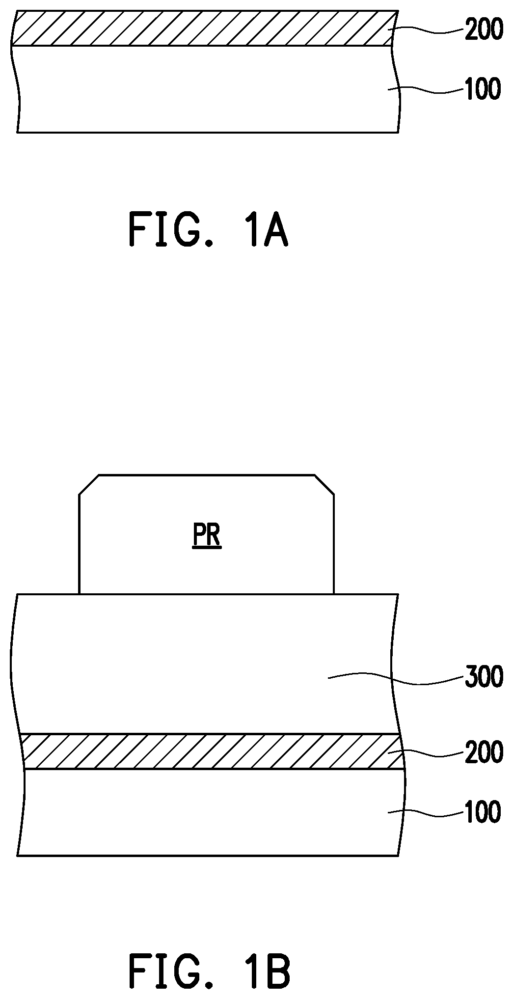
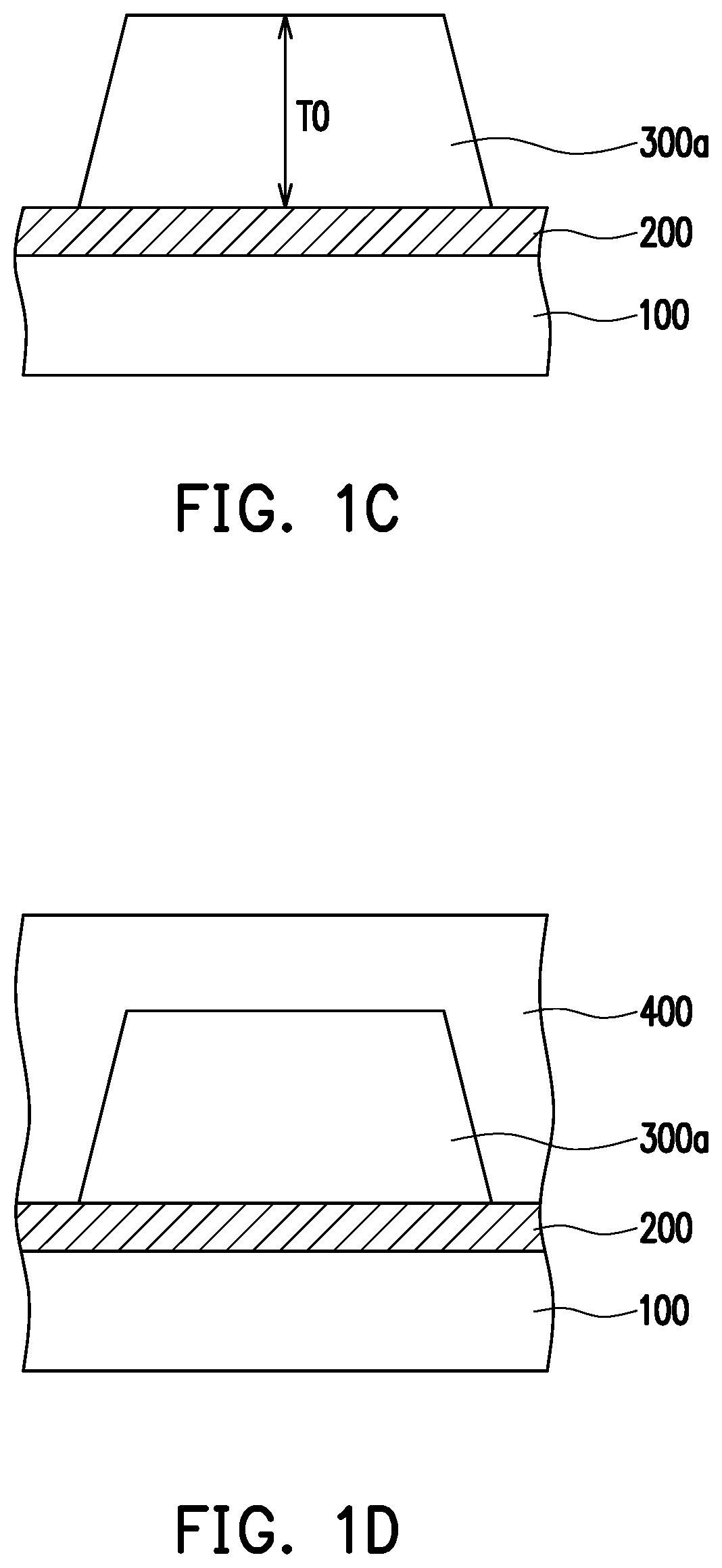
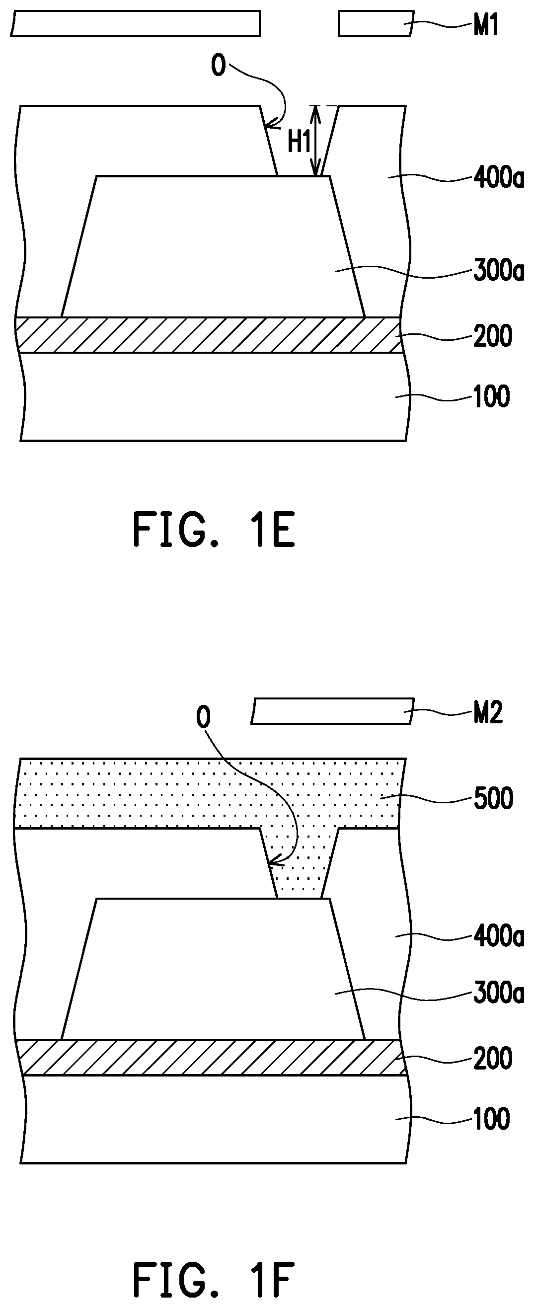
[0017]FIG. 1A to FIG. 1K are each a schematic cross-sectional view of a manufacturing method of a liquid crystal panel according to an embodiment of the invention.

[0018]Referring to FIG. 1A first, an electrode layer 200 is formed on a substrate 100. The substrate 100 is made of glass, quartz, organic polymer or other applicable materials. A thickness of the substrate 100 is, for example, hundreds of microns to several millimeters. For example, the thickness of the substrate 100 is 0.5 millimeters, but the invention is not limited thereto.

[0019]The electrode layer 200 is made of transparent conductive oxide. For example, the electrode layer 200 is made of indium tin oxide, indium zinc oxide, aluminum tin oxide, aluminum zinc oxide, indium gallium zinc oxide or a stack layer of at least two of the foregoing, but the invention is not limited thereto.

[0020]In some embodiments, other element layers are included between the electrode layer 200 and the substrate 100. Therefore, an electric...


PUM

PropertyMeasurementUnit
thicknessaaaaaaaaaa
thickness T0aaaaaaaaaa
height H1aaaaaaaaaa

Abstract

A liquid crystal panel and a manufacturing method thereof are provided. The liquid crystal panel includes a substrate, an electrode layer, an insulating layer, a first alignment layer, a second alignment layer, and a liquid crystal layer. The electrode layer is located on the substrate. The insulating layer is located on the electrode layer. The insulating layer has a cavity and an opening connected to a top portion of the cavity. The electrode layer is located below the cavity. The first alignment layer is located in the cavity and located on the electrode layer. The second alignment layer is located at the top portion of the cavity. Each of the liquid crystal layers is located in the cavity and between the first alignment layer and the second alignment layer.

Description

CROSS-REFERENCE TO RELATED APPLICATION[0001]This application claims the priority benefit of Taiwan application serial no. 108132228, filed on Sep. 6, 2019. The entirety of the above-mentioned patent application is hereby incorporated by reference herein and made a part of this specification.BACKGROUND OF THE INVENTIONField of the Invention[0002]The disclosure relates to a liquid crystal panel, and in particular, to a liquid crystal panel with a liquid crystal layer located in a cavity of an insulating layer and a manufacturing method thereof.Description of Related Art[0003]A liquid crystal display panel has advantages of a small size and low radiation, and has been widely used in a variety of electronic products. Currently, the liquid crystal display panel generally includes an upper substrate, a lower substrate, and a sealant used to connect the upper substrate and the lower substrate, where a liquid crystal is located between the upper substrate and the lower substrate, and the se...

Claims


Application Information

Patent Timeline
Patent Type & Authority Patents(United States)
IPC IPC(8): G02F1/1337G02F1/1335G02F1/1341
CPCG02F1/1337G02F1/1341G02F1/133514G02F1/133308G02F1/133345G02F1/134309G02F1/133377
Inventor SU, HSIEN-HUNGLEE, SEOK-LYULHSU, YEN-HUANG
Owner AU OPTRONICS CORP
Learn More