Mechatronic circuit-breaker device

a circuit breaker and electronic technology, applied in the direction of air breakers, high-tension/heavy-dress switches, electrical equipment, etc., can solve the problems of heavy losses and heating

Active Publication Date: 2021-06-29
GENERAL ELECTRIC TECH GMBH
View PDF13 Cites 1 Cited by
  • Summary
  • Abstract
  • Description
  • Claims
  • Application Information

AI Technical Summary

Benefits of technology

[0023]Due to the invention, the residual current in the main branch is very low. Thus, the electromechanical switch-disconnector can be opened with minimum arc levels. Accordingly, the contacts of the electromechanical switch-disconnector don't deteriorate too quickly.
[0025]This avoids the commutation of current from the auxiliary branch back into the main branch, while the value of the current can vary over a wide range and reach values of several kilo amps.

Problems solved by technology

One can assume that the flow of the main current in the static IGBT components is likely to cause heavy losses and heating.

Method used


Image

  • Mechatronic circuit-breaker device
  • Mechatronic circuit-breaker device

Examples


Embodiment Construction

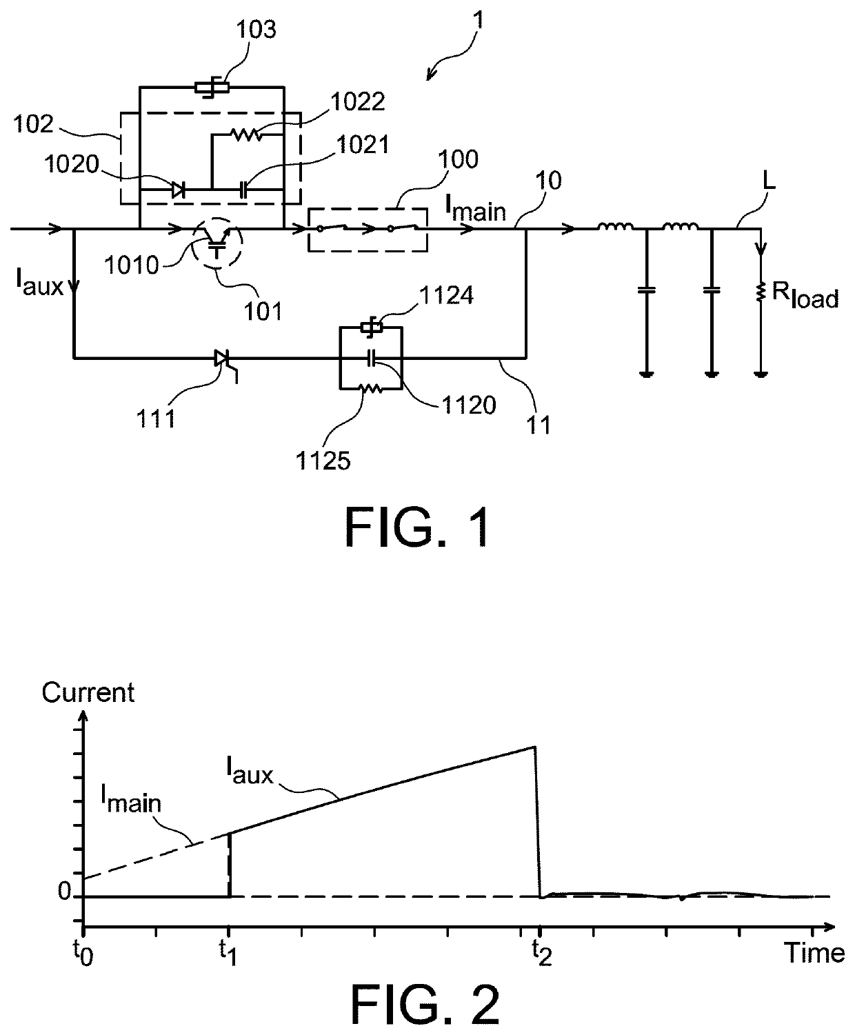
[0046]FIG. 1 shows an electrical architecture of a sub-part of a mechatronic circuit-breaker device 1 according to an embodiment of the invention intended to break high direct currents in transmission networks L in a peak-to-peak voltage range up to 320 kV DC or more, with emphasis on the main and auxiliary branches.

[0047]Such a circuit-breaker device is well known of the person skilled in the art. Consequently, only components essential to the present invention are described here.

[0048]Such a device 1 comprises firstly a main branch 10 in which the primary current flows under steady conditions.

[0049]In parallel with the main branch 10 there is provided an auxiliary branch 11.

[0050]The main branch 10 comprises an electromechanical switch-disconnector 100 consisting of two vacuum interrupters (vacuum bottles), electrically in series with a breaker cell 101. This breaker cell 101 comprises at least one power electronic switch as for example an insulated gate bipolar transistor (IGBT) ...


PUM


Abstract

The disclosure relates to a mechatronic circuit-breaker device adapted to break an electrical current flowing through electrical power transmission means, the device including a main branch comprising at least one electromechanical switch-disconnector connected in series with at least one breaker cell itself electrically in parallel with a snubber and a first voltage surge limiter; an auxiliary branch electrically in parallel with the main branch and comprising at least one power electronic switch, connected in series with at least one capacitor, itself electrically in parallel with its discharge resistance and a second voltage surge limiter. The first voltage surge limiter has a sharper voltage-current characteristic and offering a much steeper slope at low currents than the second surge limiter.

Description

FIELD OF THE INVENTION[0001]The invention relates to a mechatronic circuit-breaker device.[0002]The main target application of the invention is to breaking high direct currents in a transmission and / or distribution line, typically at peak-to-peak voltage levels exceeding 50 kilovolts (kV) (DC), up to 800 kV (DC) and beyond. The expression high-voltage direct current (HVDC) is commonly used for this field of application.[0003]The invention may also be applied to breaking direct currents at lower peak-to-peak voltages, typically in the range 1 kV to 50 kV, or to breaking alternating currents.BACKGROUND OF THE INVENTION[0004]We consider the case of a DC circuit breaker comprising a branch with a fast switch (called the main branch) separating contacts (arc tubes, vacuum interrupters). The circuit breaker also comprises an auxiliary branch.[0005]When a fault is detected on the power grid, the power flowing through the main branch switches to the auxiliary branch.[0006]The general princi...

Claims


Application Information

Patent Timeline
Patent Type & Authority Patents(United States)
IPC IPC(8): H01H9/54H02H3/087H01H33/59H02H3/02H02H9/04H02H9/00
CPCH01H9/542H01H9/548H01H33/596H02H3/021H02H3/087H02H9/04H01H2009/543H01H2009/544H02H9/001
Inventor DUPRAZ, JEAN-PIERRE
Owner GENERAL ELECTRIC TECH GMBH
Why Eureka
Try Eureka