Device for venting an explosive charge and munition equipped with such a device

a technology of explosive charge and device, which is applied in the direction of ammunition projectiles, weapons, ammunition storage, etc., can solve the problems of significant human and material consequences, explosive charge explosion in undesired manner, and exposure of weapons to attack, so as to reduce the sensitivity of weapons and be simple to manufacture and use.

Active Publication Date: 2021-07-06
THALES SA
View PDF12 Cites 0 Cited by
  • Summary
  • Abstract
  • Description
  • Claims
  • Application Information

AI Technical Summary

Benefits of technology

[0030]More particularly, it seeks to provide a venting device for venting the explosive charge for a munition projectile that makes it possible to guarantee better reduction in the sensitivity of the munition, and notably makes it possible to ensure that the munition exhibits a type-V (munition burns) or type-VI (no sustained reaction) response to a thermal attack of the slow or rapid heating type.
[0058]According to one embodiment, the venting device further comprises a first component connected to the first part of the projectile and located between said first and the second part of the projectile, the sealing means and the pushing means being located between said first component and said second part of the projectile. Said first component may act as a bearing surface for the pushing means, and may also serve to protect the explosive charge when a pushing force is applied.

Problems solved by technology

When munitions are being transported, stored or used (for example on ships, in depots, in the field of operation), there is a risk that the munitions will be exposed to attack, typically thermal attack, which may cause the explosive charge to explode in an undesired manner.
Such impromptu explosions may cause accidents and have significant human and materiel consequences.
These accidents may assume enormous proportions if, in a nearby environment, there are other weapons which may in their turn react violently, going so far as to cause nominal detonation of their own explosive charges.
The technical problem is therefore to provide munitions that offer a type-V (munition burns) or type-VI (no sustained reaction) response to a thermal attack of the slow or rapid heating type.
Specifically, when a munition does not have a sensitivity-reduction system and is subjected to thermal attack, its explosive charge will increase in temperature and may reach the cookoff temperature of said explosive charge, causing the latter first of all to burn.
Thereafter, under the effect of the confinement of the explosive charge in the body, the munition is liable to transition to a pneumatic explosion, or even a deflagration or a detonation.
In this case, it is necessary to create a weakened zone in the projectile which is able to break open quickly before the reaction of the explosive runs away, as this would rapidly lead to a violent reaction.
However, the existing devices have the following disadvantages.
Thus, the risk of runaway and of transition from a burn to an explosion and / or a deflagration and / or a detonation is high if the opening of the body is not sufficiently rapid and / or if it does not reach a sufficient size to sufficiently vent the explosive charge.
Now, once the body starts to open, or in the event of defective sealing, the melt liquid (or, respectively, the combustion gas) escapes, canceling any pressure force and thereby limiting the ability of the venting device to open.
Thus, if the opening obtained in the body is insufficient, the situation reverts to that of the first instance, with the risk of runaway and of transition from a burn to an explosion, a deflagration and / or a detonation.
As the temperature of this actuating element increases, to the point at which the pyrotechnic elements that it contains react, the effects induced may cause uncontrolled initiation of the explosive charge as a result of the proximity of the two parts.

Method used


Image

  • Device for venting an explosive charge and munition equipped with such a device
  • Device for venting an explosive charge and munition equipped with such a device
  • Device for venting an explosive charge and munition equipped with such a device

Examples


Embodiment Construction

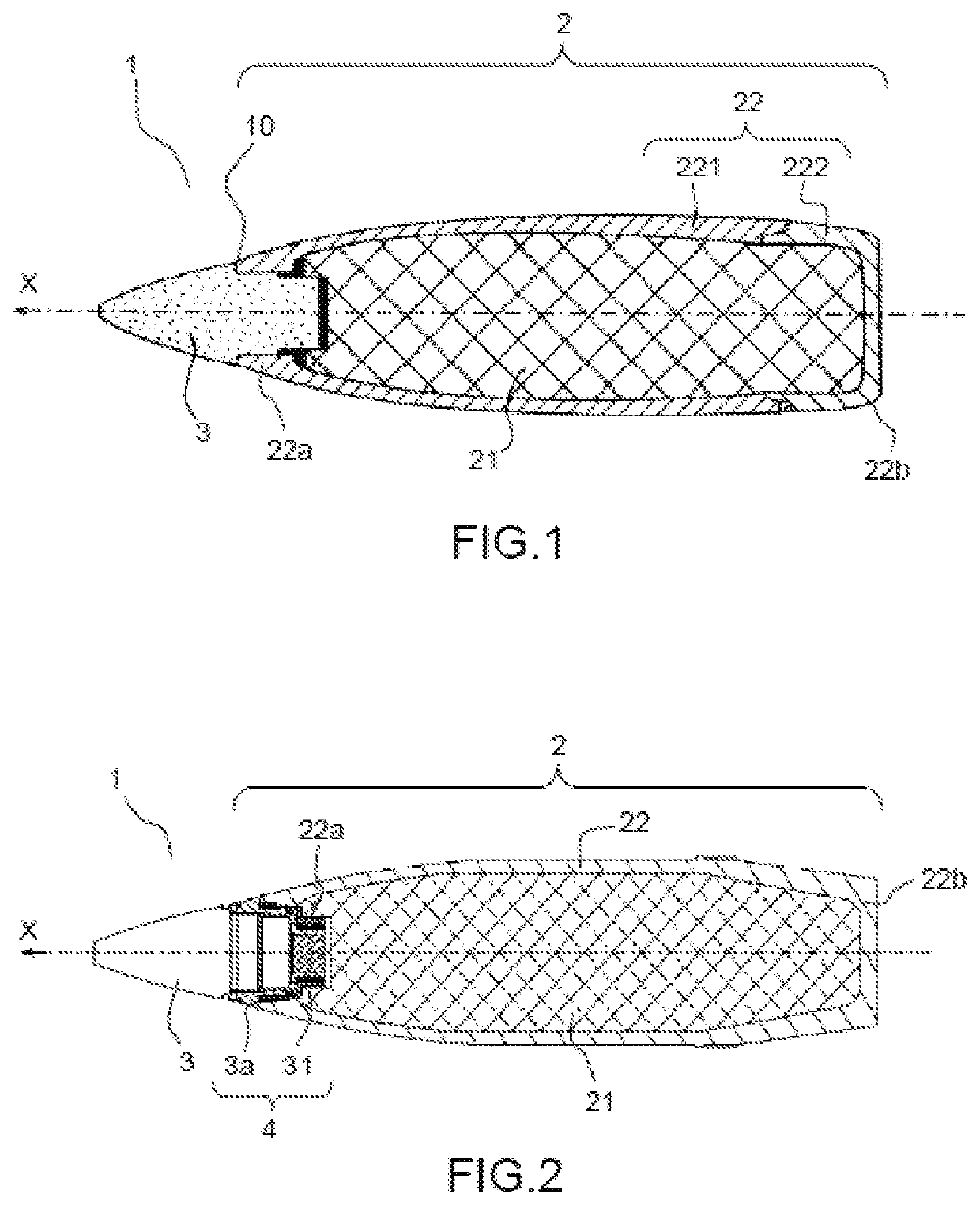
[0075]FIG. 1 was described in the “Prior art” section of the present description and will not be revisited here.

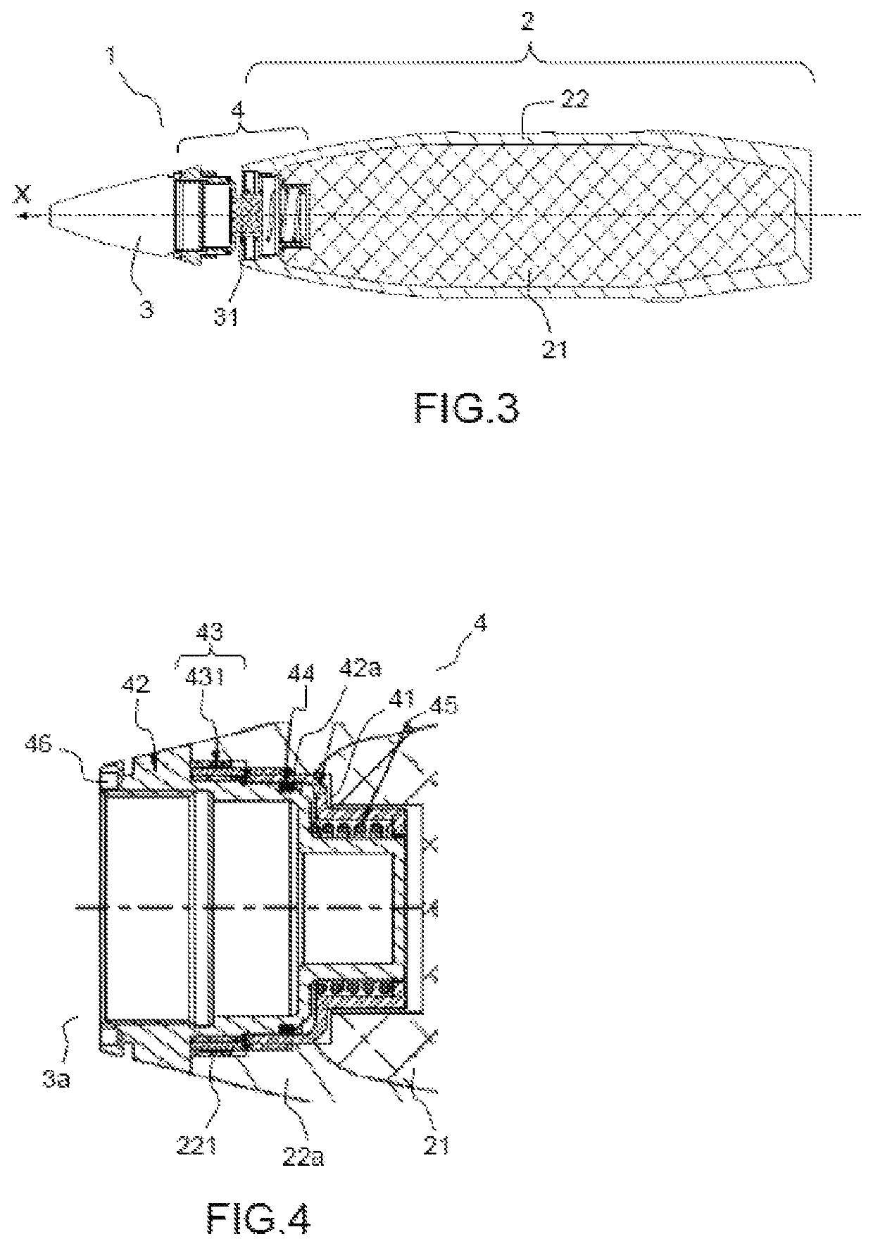
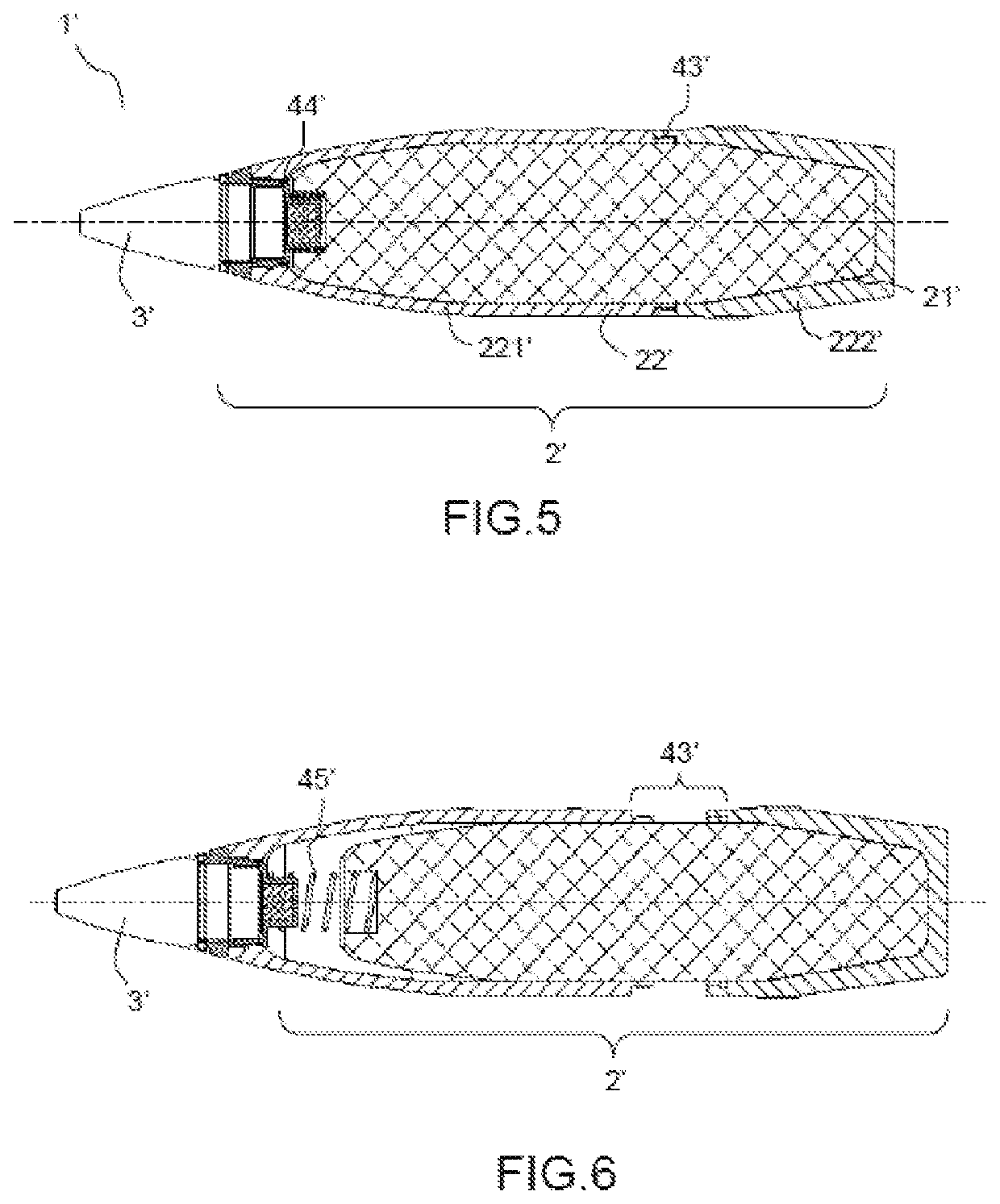
[0076]FIGS. 2, 3 and 4 depict a first example of a venting device 4 according to the invention, seen in the closed configuration (device not triggered) and in the open configuration (device triggered). They readopt the same numerical references as FIG. 1 for elements that are in common with FIG. 1.

[0077]FIGS. 2, 3 and 4 illustrate a projectile element 1 for a munition. The propulsive element of the munition has not been depicted in the figures. The projectile element 1 is an element that is elongate in the longitudinal direction X and exhibits symmetry with respect to said longitudinal direction.

[0078]The projectile element 1 comprises a first part 2 containing the explosive charge 21 and a second part 3 comprising an actuating element for triggering the explosive charge. In FIG. 2, the first and second parts are depicted as solidly joined together (in the so-called “close...


PUM


Abstract

A venting device for a projectile includes a first part comprising a body containing an explosive charge and a second part comprising an actuating element for triggering the explosive charge, the first and second parts forming an assembly able to confine the explosive charge when they are connected, the venting device comprising: a sealing means configured to render the projectile gastight and fluidtight when the first and second parts are connected; an opening means able to allow the projectile to open, the opening means being able to be triggered when the internal pressure in the projectile is higher than or equal to a given pressure threshold; a pushing means able to enlarge the opening of the projectile once the opening means has been triggered.

Description

CROSS-REFERENCE TO RELATED APPLICATIONS[0001]This application claims priority to foreign French patent application No. FR 1872833, filed on Dec. 13, 2018, the disclosure of which is incorporated by reference in its entirety.FIELD OF THE INVENTION[0002]The present invention relates to a device for venting an explosive charge.[0003]It also relates to a munition equipped with such a device.[0004]It applies notably to reducing the sensitivity of munitions by venting the explosive charge.BACKGROUND[0005]When munitions are being transported, stored or used (for example on ships, in depots, in the field of operation), there is a risk that the munitions will be exposed to attack, typically thermal attack, which may cause the explosive charge to explode in an undesired manner. Such impromptu explosions may cause accidents and have significant human and materiel consequences. These accidents may assume enormous proportions if, in a nearby environment, there are other weapons which may in thei...

Claims


Application Information

Patent Timeline
Patent Type & Authority Patents(United States)
IPC IPC(8): F42B39/20F42B12/20
CPCF42B12/207F42B39/20
Inventor BENADE, EROANSCHWARTZ, JEAN-SÉBASTIENBAILLARGEAT, ROMAIN
Owner THALES SA
Why Eureka
Try Eureka