Device and method for positioning an underwater device

a technology for underwater devices and positioning devices, applied in measurement devices, satellite radio beaconing, instruments, etc., can solve the problems of low accuracy of position determination with these systems, loss of diver who has strayed away, and complex system architectur

Active Publication Date: 2021-07-06
SUBMARINE OPEN TECH
View PDF5 Cites 0 Cited by
  • Summary
  • Abstract
  • Description
  • Claims
  • Application Information

AI Technical Summary

Benefits of technology

[0034]Thanks to these provisions, no reference buoy is necessary, and the system's architecture is not made more complex with the addition of the surface transponder. In this system, the position of the transponders is calculated directly at the underwater device, which makes it possible to eliminate the position errors due to ionospheric effects.
[0036]These embodiments make it possible to reproduce the Doppler effect of the satellite signals in the case of GPS. The Doppler effect makes the frequency of the signals vary randomly, according to the movement of the satellites. Altering the acoustic source as a function of the internal clock of the GPS receiver makes it possible to operate the location system with frequencies considered identical but altered randomly by the dynamic means of the internal clock of the GPS receiver.
[0038]These embodiments make it possible to limit the number of means utilized to produce the system.
[0043]These embodiments make it possible to transmit the pseudo-distance information without this information being binarized. The transmission of information is performed by the adaptation of a transmission parameter.

Problems solved by technology

Determining the position of divers in a body of fresh or sea water is a technical challenge because of the obstacles these environments present for the transmission of electromagnetic waves.
The consequences of this positioning problem can be the loss of a diver who has strayed away from a group of divers or from the transport craft of the diver or divers.
However, in practice, transmitting the signals sent by the satellites through the ionosphere leads to the signals being distorted, resulting in a position error that can be as high as approximately ten meters.
However, in these systems, each buoy has a position error of the order of ten meters and transmits this error to the underwater device with an additional error due to the transmission of underwater signals.
As a result, the accuracy of the position determined with these systems is low.
In addition, the reference buoy must be chosen before the start of the process, and the number of surface buoys makes the architecture of the system more complex.
These systems have several drawbacks:transporting a rigid structure on the craft reduces the space on board,transmitting position information involves the long-term transmission of messages that are lengthy and therefore likely to be incorrect or not reach the receiver,there is often only one float, which results in a limited line of sight, reducing the position accuracy,when the system comprises several floats, these floats have a relative position accuracy for each float of the order of one meter, which reduces the overall accuracy of the system.

Method used


Image

  • Device and method for positioning an underwater device
  • Device and method for positioning an underwater device

Examples


Embodiment Construction

OF REALIZATION OF THE INVENTION

[0080]The present description is given in a non-limiting way, each characteristic of an embodiment being able to be combined with any other characteristic of any other embodiment in an advantageous way.

[0081]It is now noted that the figures are not to scale.

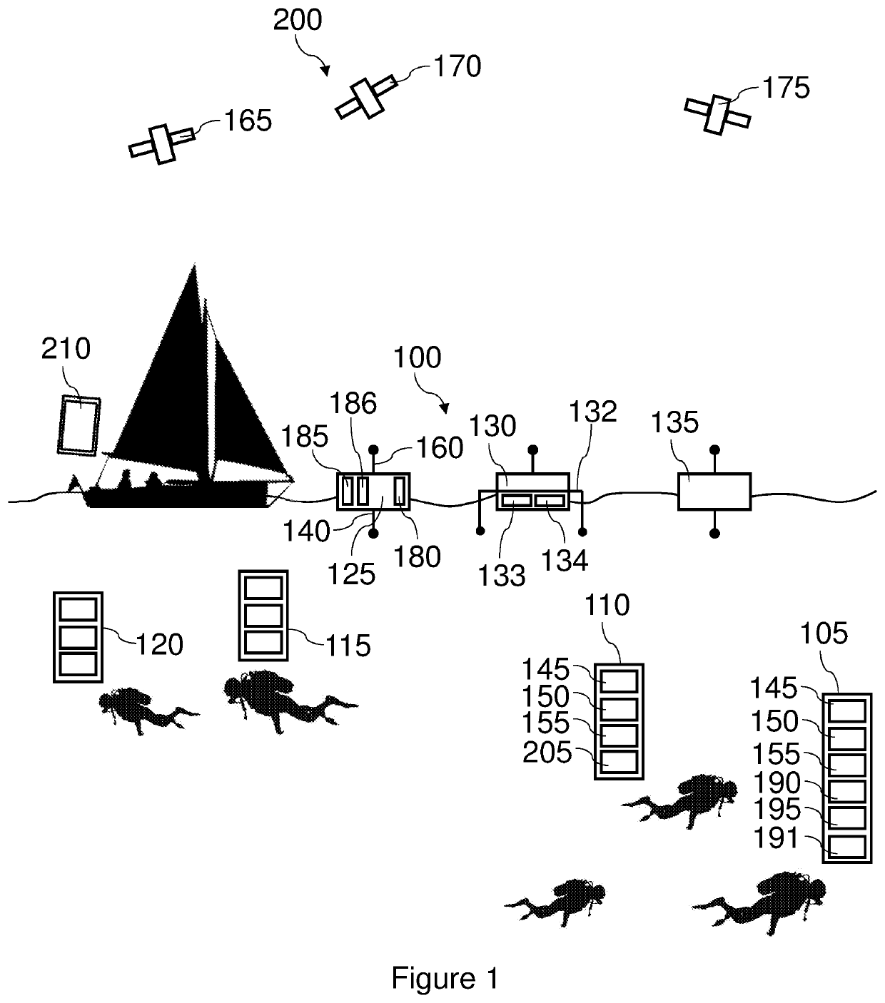
[0082]FIG. 1, which is not to scale, shows a schematic view of an embodiment of the system 100 that is the subject of the present invention. This system 100 for positioning an underwater device, 105, 110, 115 and / or 120, comprises:[0083]at least two surface transponders, 125, 130 and / or 135, each surface transponder comprising a receiver 160 of radio signals transmitted by at least two satellite sources, 165, 170 and / or 175, of signals of a geolocation system 200,[0084]each surface transponder comprising:[0085]a means 180 for estimating at least one radio pseudo-distance between the surface transponder and at least two sources of signals from the geolocation system,[0086]an attachment 185 to a float...


PUM


Abstract

The system for positioning an underwater device includingat least two surface transponders comprising a receiver for receiving radio signals transmitted by a geolocation system;each surface transponder comprising:an estimator for estimating at least one radio pseudo-distance;an attachment to a float; anda communicator for communicating information representative of the radio pseudo-distances; andan underwater acoustic transmitter;the underwater device comprising:a receiver for receiving information representative of the radio pseudo-distances;an acoustic signal receiver;a determinator for determining one or more acoustic pseudo-distances between at least two underwater acoustic transmitters and the underwater device; anda calculator for calculating the position of the device in a terrestrial frame of reference centered on one of the surface transponders.

Description

TECHNICAL FIELD OF THE INVENTION[0001]The present invention relates to a device and method for positioning an underwater device. It applies, in particular, to the location of divers or drones below the surface of the sea.STATE OF THE ART[0002]Determining the position of divers in a body of fresh or sea water is a technical challenge because of the obstacles these environments present for the transmission of electromagnetic waves.[0003]The consequences of this positioning problem can be the loss of a diver who has strayed away from a group of divers or from the transport craft of the diver or divers. In addition, the diver must be able to reach a dive site as quickly as possible, which entails indicating the position of this site to the diver.[0004]The principal of the GPS (for “Global Positioning System”) is known, in which a plurality of satellites transmit electromagnetic signals captured by a receiver on Earth, this receiver determining its position in the reference frame of the ...

Claims


Application Information

Patent Timeline
Patent Type & Authority Patents(United States)
IPC IPC(8): G01S19/45B63C11/26B63C11/48G01S5/00G01S5/30B63C11/02
CPCG01S19/45B63C11/26B63C11/48G01S5/0009G01S5/0072G01S5/30B63C2011/021
Inventor CODOL, JEAN-MARIE
Owner SUBMARINE OPEN TECH
Why Eureka
Try Eureka