
Receiver and transmitter for high speed data and low speed command signal transmissions

a high-speed command and transmission technology, applied in the field of signal transmission system, can solve the problems of inability to configure the receiver to receive the high-speed command signals normally, the disadvantage of increasing the path count and hardware implementation, and the inability to adapt to different situations. the effect of high speed

Active Publication Date: 2021-08-10
NOVATEK MICROELECTRONICS CORP
View PDF1 Cites 2 Cited by
  • Summary
  • Abstract
  • Description
  • Claims
  • Application Information

AI Technical Summary

Benefits of technology

The objective of this patent is to create a system that allows for high-speed data and low-speed command signal transmissions between a receiver and a transmitter.

Problems solved by technology

However, before the command signals are correctly received, the receiver may not be set up to receive the high speed command signals normally.
In another example, the command signals may be transmitted independently, which is accompanied by a disadvantage of increasing path counts and hardware implementations.
Alternatively, the slave device may be given with a fixed setting, which has a disadvantage that the setting cannot be configured or adjusted flexibly under different situations.

Method used


Image

  • Receiver and transmitter for high speed data and low speed command signal transmissions
  • Receiver and transmitter for high speed data and low speed command signal transmissions
  • Receiver and transmitter for high speed data and low speed command signal transmissions

Examples


Embodiment Construction

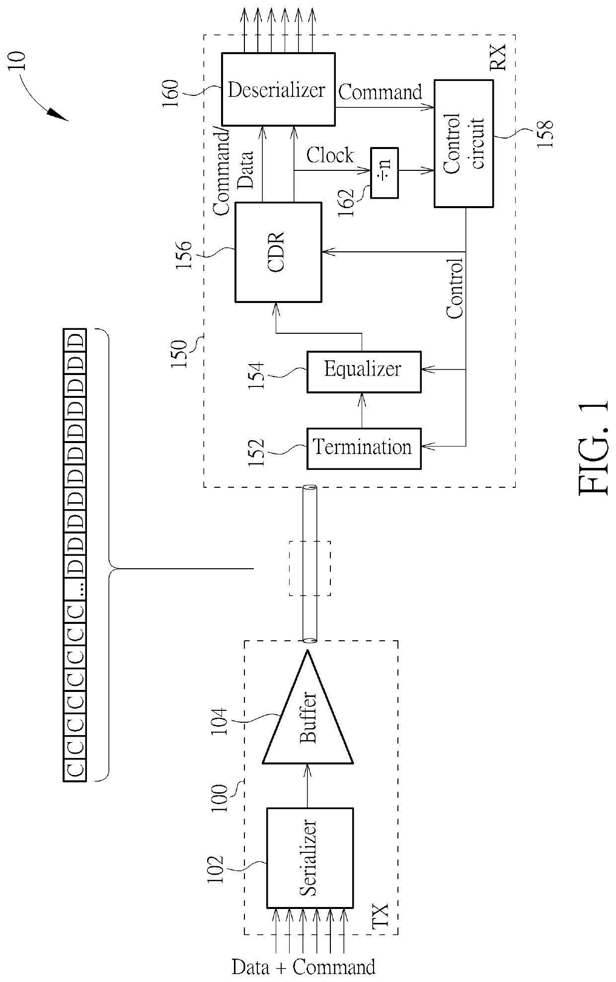
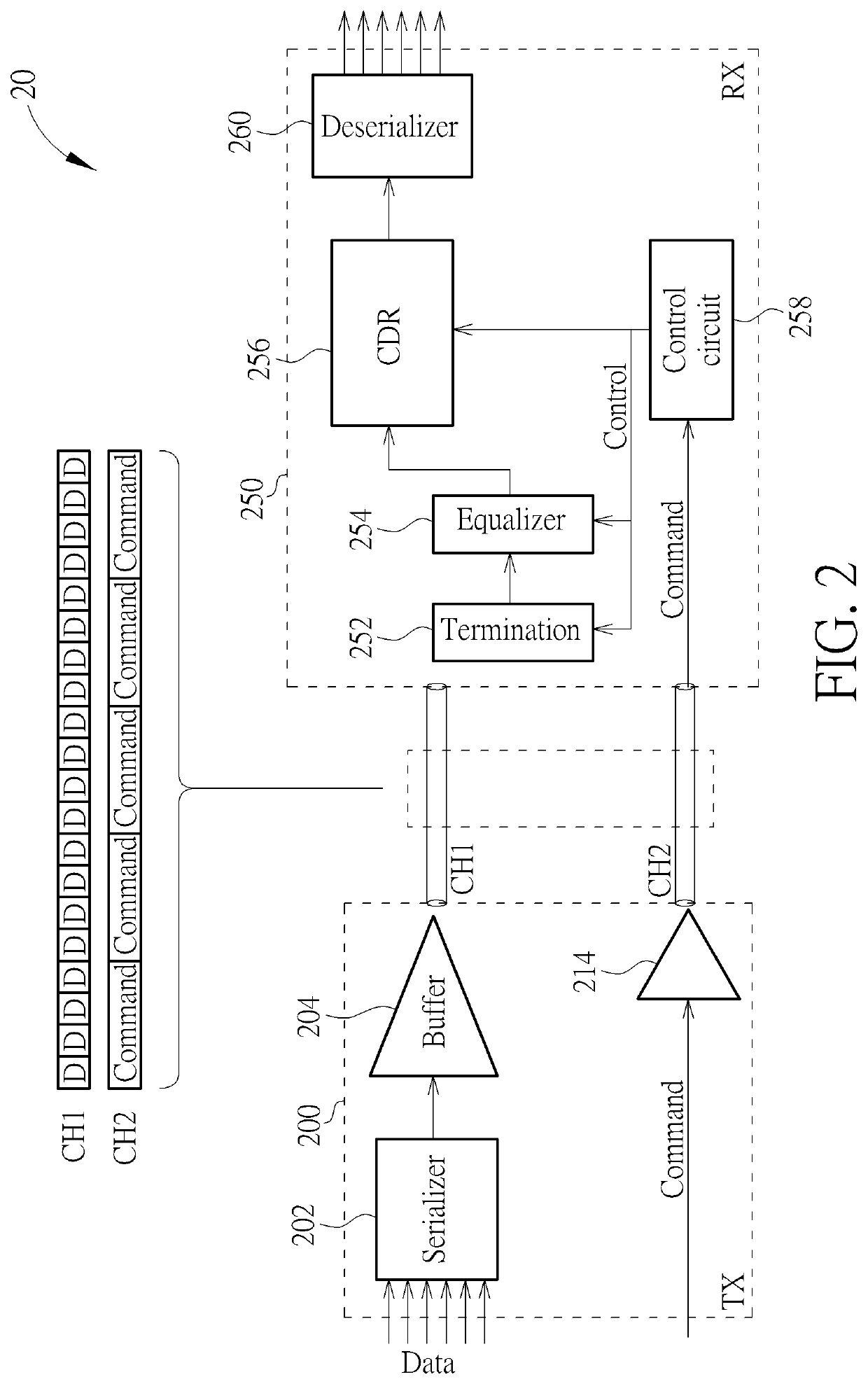
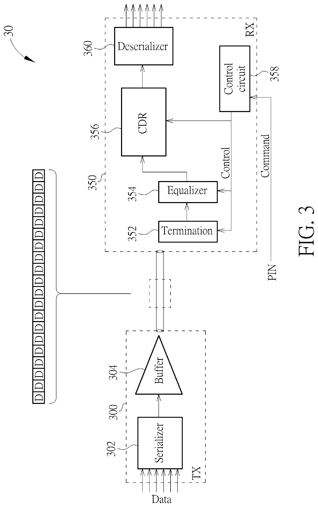
[0016]Please refer to FIG. 1, which is a schematic diagram of a signal transmission system 10. As shown in FIG. 1, the signal transmission system 10 includes a transmitter (TX) 100 and a receiver (RX) 150. The transmitter 100, which may be a master device such as a system processor on the circuit board, includes a serializer 102 and an output buffer 104. A series of command signals and a series of data signals may come from a digital circuit in the system processor, to be forwarded by the transmitter 100. The serializer 102 is configured to perform parallel to serial conversion on the command signals and the data signals, to generate the command signals and the data signals in series. The output buffer 104 is configured to output the command signals and the data signals to the receiver 150.

[0017]The receiver 150, which may be a slave device such as a functional integrated circuit (IC) on the circuit board, includes a termination circuit 152, an equalizer 154, a clock and data recove...


PUM


Abstract

A receiver is configured to receive a series of command signals and a series of data signals. The receiver includes a first clock and data recovery (CDR) circuit, a control circuit and a second CDR circuit. The first CDR circuit is configured to process the series of command signal to generate a clock signal. The control circuit, coupled to the first CDR circuit, is configured to generate a control signal according to the series of command signals and the clock signal received from the first CDR circuit. The second CDR circuit, coupled to the control circuit, is configured to process the series of data signals according to the control signal received from the control circuit.

Description

BACKGROUND OF THE INVENTION1. Field of the Invention[0001]The present invention relates to a signal transmission system, and more particularly, to a signal transmission system having a receiver and a transmitter capable of high speed data and low speed command signal transmissions.2. Description of the Prior Art[0002]In the conventional signal transmission system on a circuit board, after power-on, the master device should send command signals to control the slave device to start its operation, and then data signals can be forwarded between the master device and the slave device.[0003]There are several signal transmission methods commonly used in the signal transmission system. In an example, the command signals may be transmitted with the same signal rate as high speed data to realize a high speed serial transmission. However, before the command signals are correctly received, the receiver may not be set up to receive the high speed command signals normally. In another example, the...

Claims


Application Information

Patent Timeline
IPC IPC(8): H04L7/04H04L7/027
CPCH04L7/027H04B1/16H04B1/04H04L7/0079H04L7/06H04L7/0091H04L25/493
Inventor FANG, YONG-RENWANG, YU-HSIANGYEH, CHE-WEI
Owner NOVATEK MICROELECTRONICS CORP
Learn More