
System for controlling construction machinery and method for controlling construction machinery

a technology of construction machinery and control system, which is applied in the direction of mechanical equipment, servomotors, transportation and packaging, etc., can solve the problems of fuel efficiency decline, inefficient flow distribution, and deterioration in controllability, so as to maximize work efficiency and improve user convenien

Active Publication Date: 2021-08-31
HD HYUNDAI INFRACORE CO LTD
View PDF13 Cites 5 Cited by
  • Summary
  • Abstract
  • Description
  • Claims
  • Application Information

AI Technical Summary

Benefits of technology

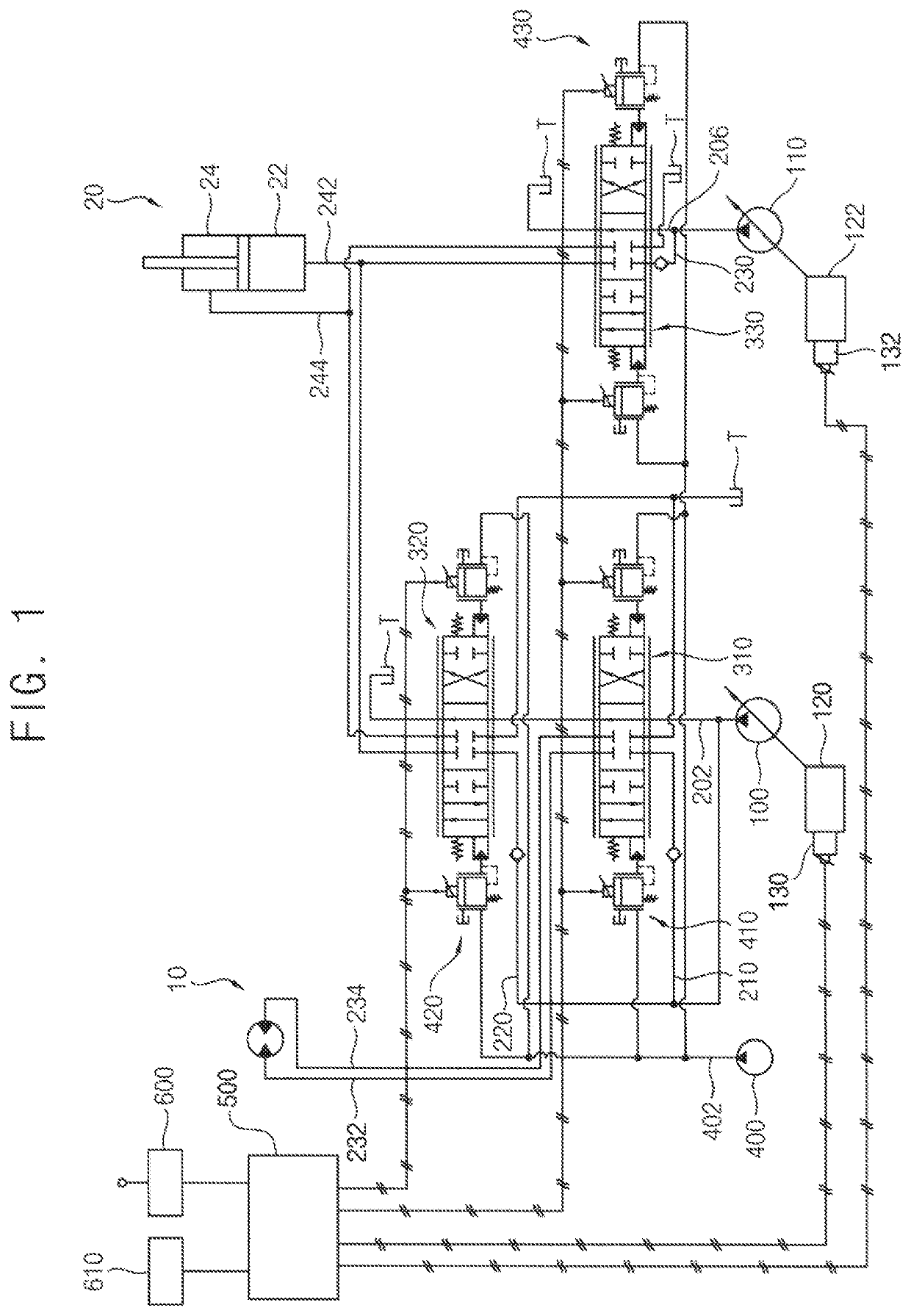
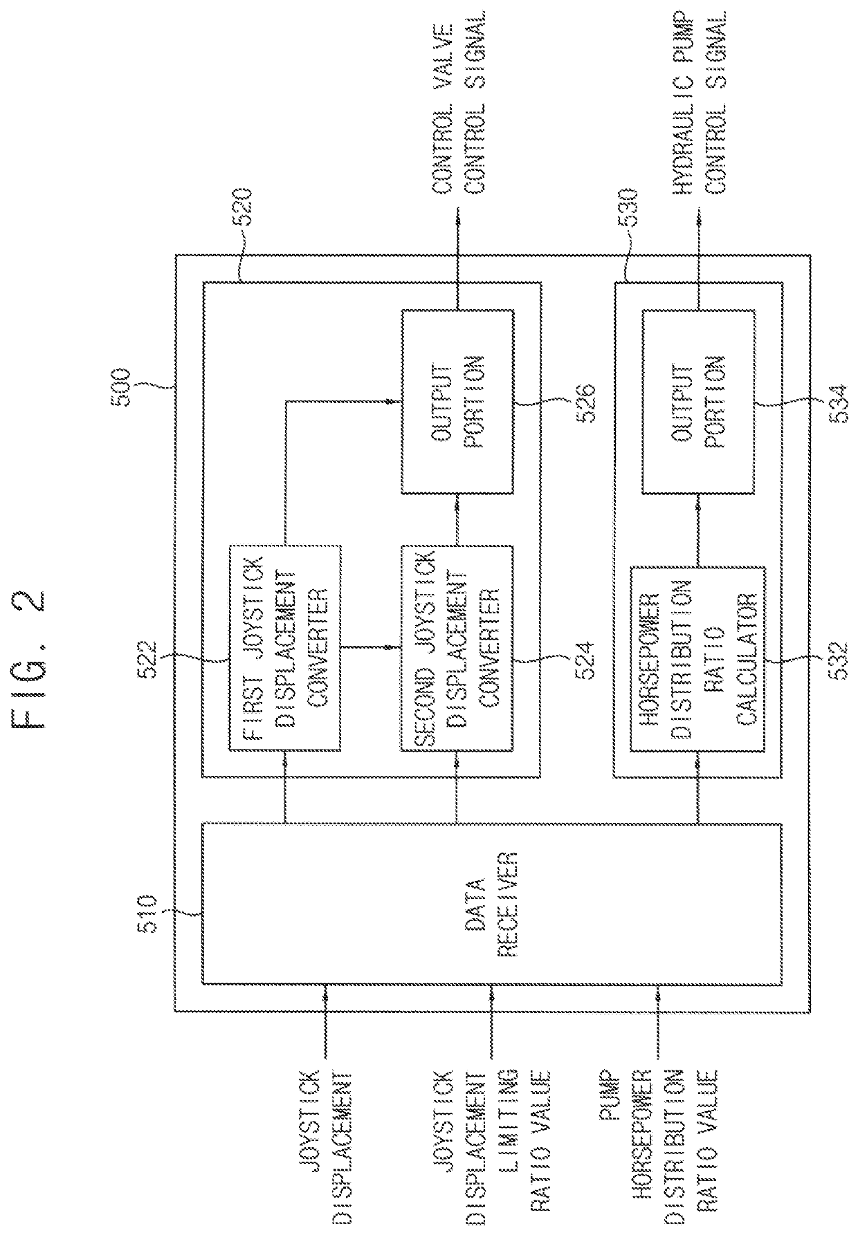
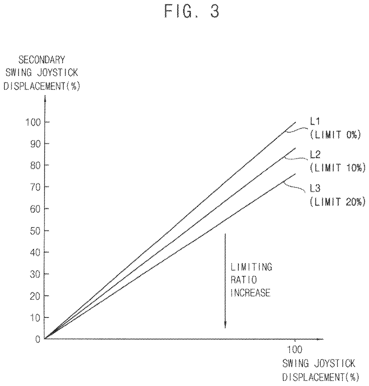
[0024]According to example embodiments, a horsepower distribution ratio of first and second hydraulic pumps may be controlled according to a pump horsepower distribution ratio selected by an operator, and even when the first and second hydraulic pumps are operated according to the pump horsepower distribution ratio, a spool displacement of a swing control valve may be limited according to a limiting ratio of a swing joystick displacement selected by the operator to control a swing orifice area. Further, a spool displacement of a boom control valve may be limited according to the limited swing joystick displacement to control a boom orifice area.
[0025]Accordingly, an orifice area ratio of the hydraulic lines though which a working oil is supplied to the actuators may be controlled by performing the pump power distribution control and the spool displacement control of the control valve using EPPRV, a speed balance between the actuators may be adjusted to match user's situation in a variety of working conditions. Thus, user convenience may be improved and work efficiency may be maximized.
[0026]However, the effect of the invention may not be limited thereto, and may be expanded without being deviated from the concept and the scope of the present invention.

Problems solved by technology

However, inefficient flow distribution and deterioration in controllability may occur due to a fixed orifice area in the orifice structure, and when a relatively great load is exerted on the actuator, fuel efficiency may be decreased due to pressure loss.

Method used


Image

  • System for controlling construction machinery and method for controlling construction machinery
  • System for controlling construction machinery and method for controlling construction machinery
  • System for controlling construction machinery and method for controlling construction machinery

Examples


Embodiment Construction

[0035]Hereinafter, preferable embodiments of the present invention will be explained in detail with reference to the accompanying drawings.

[0036]In the drawings, the sizes and relative sizes of components or elements may be exaggerated for clarity.

[0037]It will be understood that, although the terms first, second, third, etc. may be used herein to describe various elements, components, regions, layers and / or sections, these elements, components, regions, layers and / or sections should not be limited by these terms. These terms are only used to distinguish one element, component, region, layer or section from another element, component, region, layer or section. Thus, a first element, component, region, layer or section discussed below could be termed a second element, component, region, layer or section without departing from the teachings of example embodiments.

[0038]The terminology used herein is for the purpose of describing particular example embodiments only and is not intended ...


PUM


Abstract

A control system for construction machinery, includes a hydraulic pump, first and second actuators connected to the hydraulic pump through first and second parallel lines respectively, first and second control valves installed in the first and second parallel lines respectively and configured to control operations of the first and second actuators, first and second spool displacement adjusting valves configured to control displacement amounts of the spools of the first and second control valves, and a control valve control portion configured to output the control signal, and configured to limit a maximum allowable value of the manipulation signal for the first actuator to a value selected by the operator and limit a spool displacement amount of the second control valve according to the limited manipulation signal for the first actuator when the manipulation signal for a multiple operation of the first and second actuators is received.

Description

CROSS REFERENCE TO RELATED APPLICATION[0001]This present application is a national stage filing under 35 U.S.C § 371 of PCT application number PCT / KR2017 / 010012 filed on Sep. 12, 2017 which is based upon and claims the benefit of priority to Korean Patent Application No. 10-2016-0117496 filed on Sep. 12, 2016 in the Korean Intellectual Property Office. The disclosures of the above-listed applications are hereby incorporated by reference herein in their entirety.TECHNICAL FIELD[0002]The present invention relates to a control system for construction machinery and a control method for construction machinery. More particularly, the present invention relates to a control system for construction machinery including an electro-hydraulic main control valve using an electro proportional pressure reducing valve and a control method for construction machinery using the same.BACKGROUND ART[0003]Recently, in construction machinery, an electro-hydraulic main control valve with an electro proporti...

Claims


Application Information

Patent Timeline
Patent Type & Authority Patents(United States)
IPC IPC(8): F15B11/17
CPCF15B11/17F15B2211/6658F15B13/02E02F9/2242E02F9/2235E02F9/2228E02F9/2296E02F9/2292E02F9/2285E02F9/2282E02F9/2221E02F9/2267F15B13/025F15B2211/20576B60Y2200/412
Inventor KIM, CHANG-MOOKJUNG, WOO-YONGAHN, HYEON-SIKKIM, KI-YONG
Owner HD HYUNDAI INFRACORE CO LTD
Learn More