
Cable or flexible pipe with improved tensile elements

a flexible pipe and tensile element technology, applied in the direction of cables, elevators, insulated conductors, etc., can solve the problems of heavy cable, weak gripping force of the payoff system, and substantial cable elongation, so as to reduce weight, increase the strength of a tensile element, and reduce the effect of functionality

Active Publication Date: 2021-08-31
PRYSMIAN SPA
View PDF41 Cites 0 Cited by
  • Summary
  • Abstract
  • Description
  • Claims
  • Application Information

AI Technical Summary

Benefits of technology

The patent text discusses the problem of providing a tensile member for a submarine cable that can withstand high depths and can be easily connected to end fittings. The solution provided is a reinforced composite polymer in a thermoplastic matrix that offers higher impact resistance against crush failure.

Problems solved by technology

A given cable weight can cause a substantial cable elongation (e.g. greater than 0.5%) likely to damage to the cable itself.
The heavier the cable is, the stronger the gripping force of the payoff system needs to be.
Crush failure caused by gripping is a known mode of failure.
Applicant observed that tensile elements made of a fibre composite material coated with a polymeric material cannot be plastically deformed without losing or decreasing in functionality.
If the elongated tensile elements are wholly made of polymeric material, their substantial lack of plastic deformation can also cause problems at the cable ends where, free from constrain, the element can straighten and unwind, causing problems in the cable handling.

Method used


Image

  • Cable or flexible pipe with improved tensile elements
  • Cable or flexible pipe with improved tensile elements
  • Cable or flexible pipe with improved tensile elements

Examples


example 1

[0084]An elongated tensile element (reference element) made of steel only has been taken as comparative element. This tensile element has a substantially rectangular cross section with dimensions of 2 mm×7 mm, an elastic modulus of 191 GPa and a density of 7.8 g / cm3.

[0085]When a length of 1,430 m of this all steel elongated tensile element was suspended vertically, its own weight (156 kg) caused an elongation of the steel tensile element itself of 0.05%.

[0086]A first elongated tensile element according to embodiments of the present invention has been tested. This tensile element had a substantially rectangular cross section and dimensions of 2 mm×7 mm, a core made of epoxy resin reinforced with carbon fibres having an elastic modulus of 150 GPa and a density of 1.6 g / cm3, and steel sheath having an elastic modulus of 191 GPa and a density of 7.8 g / cm3. The core had a substantially rectangular cross section with dimensions of 0.75 mm×6 mm, and it was totally covered by the steel slee...

example 2

[0096]Elongated tensile elements comprising a fibre reinforced polymeric composite core, a metal sheath totally covering the composite core, a substantially rectangular cross section and dimensions of 2 mm×7 mm were bent for obtaining a deformation with a final bending diameter of 60 mm at most.

[0097]The strain applied to each element took into account the elongation at break. Such strain was significantly lower than the fibre elongation at break to preserve the integrity of the elongated element core.

[0098]

TABLE 2Fibre elasticApplied strainFinalCompositeCore sizemodulusSteel(bendingbendingNo.fibres(mm)(GPa)%radius)radius1Carbon0.5 × 615078.51.2%27.1mm(20.8 mm)2Carbon0.75 × 6 150681.7%29.6mm(22.1 mm)3Carbon 1 × 6150571.7%45.1mm(29.4 mm)4Aramid0.5 × 610078.51.2%27mm(20.8 mm)5Aramid 1 × 6100572.3%29.4mm(21.7 mm)6Glass 1 × 670572.3%28.9mm(21.7 mm)7Glass1.5 × 670362.8%42.7mm(26.8 mm)

[0099]Among the elongated tensile elements tested, No. 3 and No. 7 could not be bent with a final bending...


PUM

PropertyMeasurementUnit
elastic modulusaaaaaaaaaa
elongationaaaaaaaaaa

Abstract

A cable includes an elongated tensile element having a cross section area and including a fibre reinforced polymer composite core having an elastic modulus of at least 70 GPa and a sheath at least partially covering the composite core. The sheath is made of metal and is at least 30% of the cross section area of the tensile element.

Description

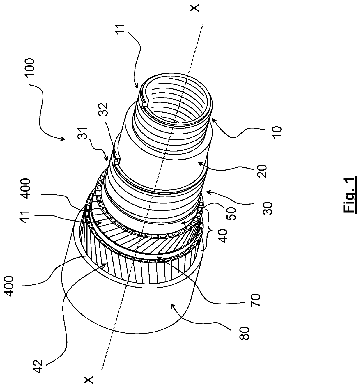
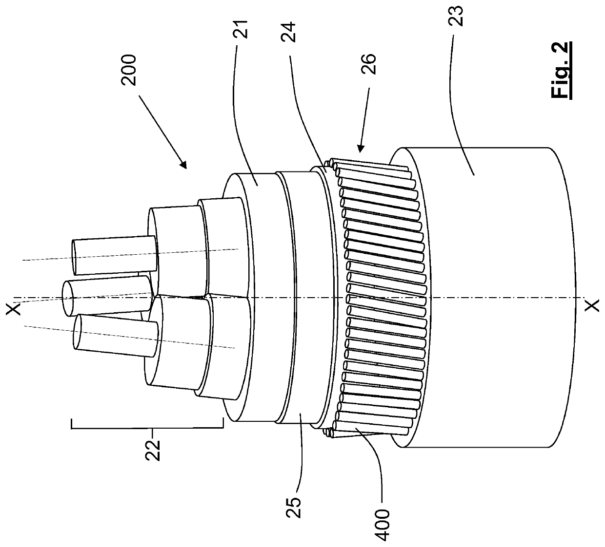
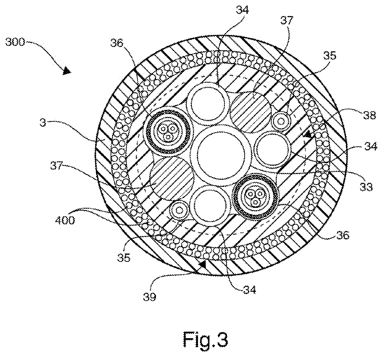
BACKGROUND[0001]The present invention relates to the field of cables and flexible pipes, in particular for submarine applications and more in particular for submarine applications in deep water. In particular the present invention relates to a cable or a flexible pipe with improved tensile elements.PRIOR ART[0002]Optical cables, power cables, umbilical cables, flexible pipes for submarine applications are well known in the art. In particular, flexible pipes comprise a tube for safely transporting a fluid, such as crude oil or gas, in a confined manner.[0003]For the purpose of the present invention, unless otherwise specified, the terms “submarine cable”, “cable for sub-sea applications” (or any similar language) or simply “cable” will include an elongated flexible element configured to transport power and / or telecommunication signals and / or one or more fluids. For the purpose of the present invention, the term “cable” will include, for instance, power cable, optical cable, flexible ...

Claims


Application Information

Patent Timeline
Patent Type & Authority Patents(United States)
IPC IPC(8): H01B7/02H01B7/18D07B1/00F16L11/08H01B7/04F16L33/01
CPCH01B7/182D07B1/005F16L11/083H01B7/045H01B7/1875F16L33/01F16L11/127D07B1/147D07B2201/2043D07B2205/3025D07B2205/3021D07B2401/205D07B2501/2007D07B2801/18
Inventor PARRIS, DONALD RAYBECHIS, MASSIMO
Owner PRYSMIAN SPA
Learn More