Grinding apparatus and grinding method

a technology of grinding apparatus and main spindle, which is applied in the direction of grinding machine components, grinding machines, manufacturing tools, etc., can solve the problem of not being able to determine the occurrence of slippage between the workpiece and the main spindle, and achieve the effect of reliably determining the occurrence of slippag

Active Publication Date: 2021-09-14
JTEKT CORP
View PDF7 Cites 2 Cited by
  • Summary
  • Abstract
  • Description
  • Claims
  • Application Information

AI Technical Summary

Benefits of technology

[0007]It is an object of the present invention to provide a grinding apparatus and a grinding method that are capable of reliably determining the occurrence of the slip between the workpiece and the main spindles.
[0014]In the grinding operation, when the grinding wheel held on the wheel spindle stock is infed into the workpiece at a constant feed rate of the wheel spindle stock, the grinding resistance moment or the drive current for each rotational angle of the workpiece tends to rise before settling and tends to remain at the same level after settling, if the slip does not occur between the workpiece and the main spindles. Since the grinding apparatus of the present aspect monitors the grinding resistance moment or the drive current for each rotational phase (angle) of the workpiece, the occurrence of the slip between the workpiece and the main spindles can be reliably determined. Consequently, a defective product of the workpiece can be prevented from flowing out, and the safety margin for the grinding conditions can be reduced to shorten the machining time.
[0020]a determination step of determining a slip between the workpiece and the main spindles based on the grinding resistance moment or the drive current at a current rotational phase, and on the grinding resistance moment or the drive current at the same phase as the current rotational phase of a previous time. According to the grinding method of the above-described aspect, the same effects as the effects of the grinding apparatus described above can be obtained.

Problems solved by technology

However, the grinding apparatus described in JP 5402347 mentioned above controls the grinding by setting a constant threshold, and consequently, cannot determine the occurrence of the slip between the workpiece and the main spindles, in some cases.

Method used


Image

  • Grinding apparatus and grinding method
  • Grinding apparatus and grinding method
  • Grinding apparatus and grinding method

Examples


Embodiment Construction

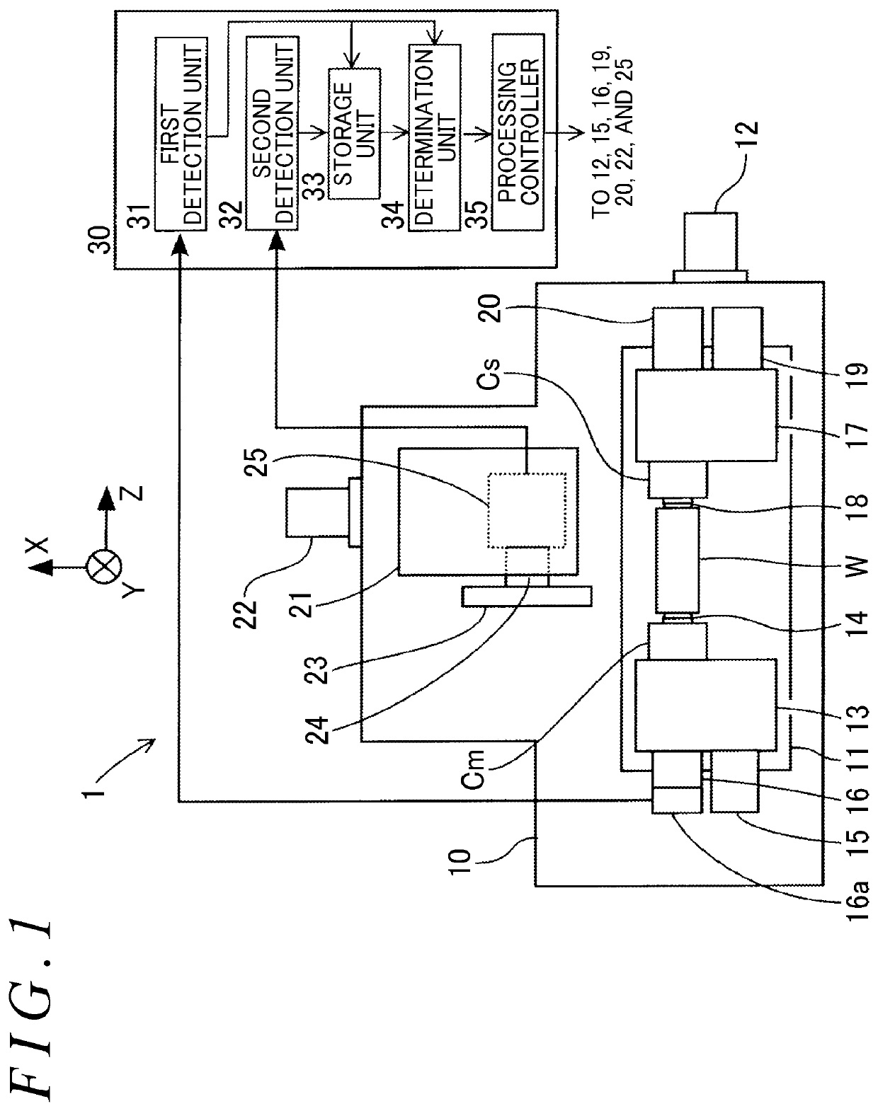
[0038]The following describes a wheel spindle stock traverse cylindrical grinding apparatus as an example of a grinding apparatus of an embodiment of the present invention. As illustrated in FIG. 1, a grinding apparatus 1 includes, for example, a bed 10, a table 11, a headstock 13, a tailstock 17, a wheel spindle stock 21, and a control device 30.

[0039]The table 11 is guidingly supported on the bed 10 so as to be movable in the Z-axis direction (right-left direction in FIG. 1) by a Z-axis servo motor 12. The headstock 13 for rotatably pivotally supporting a master spindle Cm is placed on the table 11. A center 14 (holding unit) for supporting an end of a workpiece W is mounted at a distal end of the master spindle Cm. The master spindle Cm is advanced and retreated by a predetermined amount in the axis line direction thereof by an advance / retreat drive device 15, and is rotationally driven by a master servo motor 16 (rotary drive unit).

[0040]In addition, the tailstock 17 is placed o...


PUM

PropertyMeasurementUnit
angleaaaaaaaaaa
angleaaaaaaaaaa
angleaaaaaaaaaa

Abstract

A grinding apparatus grinds a workpiece by rotating the workpiece held by main spindles and a grinding wheel held by a wheel spindle, and by relatively moving the grinding wheel toward and away from the workpiece. The grinding apparatus includes a first detection unit that detects a rotational phase of the workpiece; a second detection unit that detects a grinding resistance moment at a grinding point between the grinding wheel and the workpiece, or detects a drive current of a rotary drive unit of the workpiece or a rotary drive unit of the grinding wheel; a storage unit that stores the grinding resistance moment or the drive current in a manner associated with the rotational phase; and a determination unit that determines a slip between the workpiece and the main spindles based on the grinding resistance moment or the drive current at a current rotational phase, and on the grinding resistance moment or the drive current at the same phase as the current rotational phase of a previous time.

Description

INCORPORATION BY REFERENCE[0001]The disclosure of Japanese Patent Application No. 2017-001301 filed on Jan. 6, 2017 including the specification, drawings and abstract, is incorporated herein by reference in its entirety.BACKGROUND OF THE INVENTION1. Field of the Invention[0002]The present invention relates to a grinding apparatus and a grinding method.2. Description of Related Art[0003]Some grinding apparatuses employ a drive system in which both end faces of a workpiece are pressed to be held by centers provided on main spindles, and rotation of the centers is transmitted to the workpiece with frictional forces associated with pressing forces of the centers. Other grinding apparatuses employ a drive system in which a circumferential surface of the workpiece is pressed to be held by a chuck or a work carry provided on a main spindle, and rotation of the chuck or the work carry is transmitted to the workpiece with a frictional force associated with pressing force of the chuck or the ...

Claims


Application Information

Patent Timeline
Patent Type & Authority Patents(United States)
IPC IPC(8): B24B41/06B24B5/04B24B49/16B24B49/10B24B49/00B24B19/12
CPCB24B41/062B24B5/04B24B5/045B24B19/125B24B49/003B24B49/10B24B49/16B24B1/00B24B27/00B24B27/0092
Inventor WATANABE, AKIRA
Owner JTEKT CORP
Why Eureka
Try Eureka