Monitoring a hydrodynamic clutch

a hydrodynamic clutch and monitoring technology, applied in the direction of fluid couplings, gearings, couplings, etc., can solve the problem that the temperature parameter of an operational condition of a hydrodynamic clutch is often insufficient for a determination of efficiency or stability

Active Publication Date: 2021-09-14
VOITH PATENT GMBH
View PDF17 Cites 0 Cited by
  • Summary
  • Abstract
  • Description
  • Claims
  • Application Information

AI Technical Summary

Benefits of technology

[0008]In other embodiments, additional parameters of the clutch can furthermore be determined. All parameters may be determined on the basis of the determined temperature. Using several parameters, the operating status of the clutch can be better specified or predicted. The operating status can in particular indicate a current load, a current load capacity or wear and tear that has already occurred. Depending on the determined operating status, planning of scheduled maintenance intervals can be improved. Improved maintenance intervals can be established in such a way that components which need to be renewed can be replaced early enough, as to avoid reduced efficiency or defects, but at the same time can be long enough to ensure the serviceability of the clutch and to save on costs. By adhering to the established maintenance intervals, the clutch can again be brought into a condition of full efficiency, wherein the original efficiency can again be attained. Establishing the parameters can take into account performed maintenance on the clutch.
[0009]In one embodiment, a remaining life span is moreover determined. The method thereby includes additional steps of determining loads on the fluid for the sensed temperatures, determining a sum of the loads and determining the remaining life span on the basis of the sum. A soon to be occurring maintenance interval for the fluid can thus be determined simply and reliably. A reduction of the efficiency of the fluid determined on the basis of the thermal load on the fluid. The thermal load can reflect the mechanical load of the fluid in a sufficiently good approximation, so that a realistic assessment can be made.
[0011]When determining the remaining life span of the antifriction bearing, a frequency of starts can be considered. Starting, in other words an increase in the speed differential of the antifriction bearing from standstill to a rated speed substantially shortens the life span. The frequency of starts can be related to the life span up to the present or a frequency of start processes within a predetermined time period can be considered. Assessment of the remaining life span can thus be clearly improved.
[0018]Another embodiment includes a hydrodynamic clutch having an input side and an output side, the rotational motions of which are coupled with one another by a hydraulic fluid, a temperature sensor for period sensing of a temperature of the hydraulic fluid and the control unit described above. The clutch system can be self-contained and can facilitate transfer of torque with simultaneously improved monitoring of an operational status.

Problems solved by technology

However, the temperature as a parameter of an operational condition of the hydrodynamic clutch is oftentimes insufficient for a determination of the efficiency or stability of the clutch or respectively the drive.

Method used


Image

  • Monitoring a hydrodynamic clutch
  • Monitoring a hydrodynamic clutch
  • Monitoring a hydrodynamic clutch

Examples


Embodiment Construction

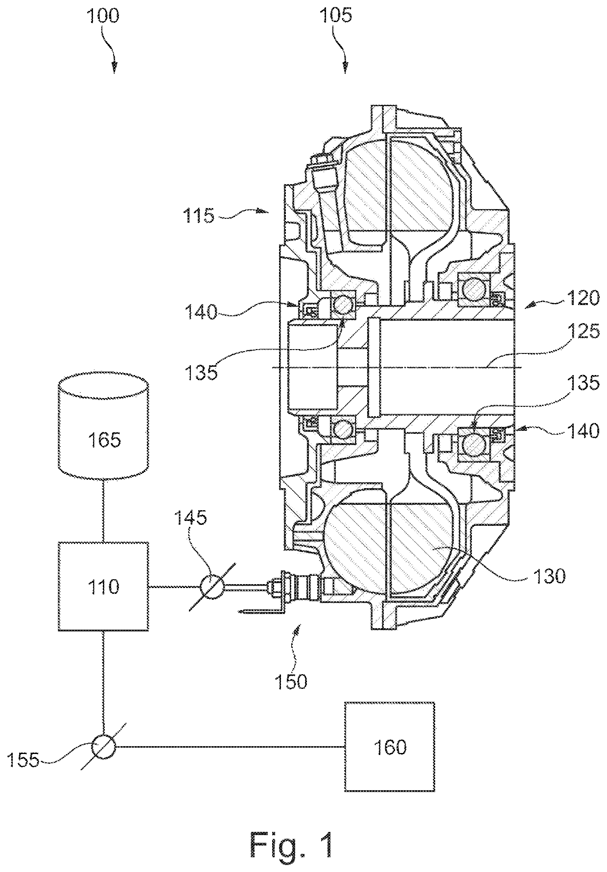
[0028]Referring now to the drawings, and more particularly to FIG. 1, there is shown a clutch system 100 having a hydrodynamic clutch 105 and a control unit 110. Clutch 105 has an input side 115 and an output side 120 which together are rotatably mounted around a common axis of rotation 125. A hydraulic fluid 130 produces a torque coupling between input side 115 and output side 120. Input side 115 is mounted opposite to output side 120 with at least one antifriction bearing 135. Depending upon a clutch type, the connections for introduction and termination of torque loads on the antifriction bearings 135 can vary, even if their arrangement is unchanged. One or more seals 140, which can include various materials, can be provided between input side 115 and output side 120.

[0029]Clutch 105 may be available in one or several predefined embodiments. Clutch system 100 can for example be used with clutches 105 having different, predetermined diameters in a range of approximately 154 to 115...


PUM


Abstract

A hydrodynamic clutch having an input side and an output side, the rotational motions of which are coupled to one another with a hydraulic fluid. A method for determining the degree of filling of the hydrodynamic clutch with fluid including steps of periodically sensing a fluid temperature of the hydraulic fluid, determining the thermal output supplied to the clutch on the basis of the temperature, determining a lambda value on the basis of the thermal output and determining the degree of filling on the basis of the lambda value.

Description

CROSS REFERENCE TO RELATED APPLICATIONS[0001]This is a continuation of PCT application No. PCT / EP2017 / 066743, entitled “MONITORING A HYDRODYNAMIC CLUTCH”, filed Jul. 5, 2017, which is incorporated herein by reference.BACKGROUND OF THE INVENTION1. Field of the Invention[0002]The present invention relates to a hydrodynamic clutch, and in more particularly to monitoring of a hydrodynamic clutch.2. Description of the Related Art[0003]A hydrodynamic clutch is configured to transfer torque between an input side and an output side. For this purpose, the input side is connected with a pump wheel and the output side is connected with a turbine wheel, wherein the impeller and the turbine wheel are coupled with one another via a hydrodynamic fluid. If the clutch is operated with slippage, for example during ramping up so that the output side rotates at a different speed than the input side, the fluid is heated. If the temperature of the fluid exceeds a predetermined value, the load of the work...

Claims


Application Information

Patent Timeline
Patent Type & Authority Patents(United States)
IPC IPC(8): F16D33/16F16D33/08F16D33/18F16H41/24F16H61/478
CPCF16D33/16F16D33/08F16D33/18F16H41/24F16H61/478F16D2500/10487F16D2500/3056F16D2500/5035F16D2500/50296F16D2500/5102F16D2500/7101
Inventor HOFFELD, HARALD
Owner VOITH PATENT GMBH
Why Eureka
Try Eureka