
Colored flame emitting device

a flame-emitting device and flame-emitting technology, which is applied in the direction of candles, lighting and heating apparatus, candle ingredients, etc., can solve the problems of in-between hues, inability to provide a broad spectrum of primary colors, and limited physical size of colored flames emitted by existing devices

Active Publication Date: 2021-09-14
WET ENTERPRISES
View PDF7 Cites 0 Cited by
  • Summary
  • Abstract
  • Description
  • Claims
  • Application Information

AI Technical Summary

Benefits of technology

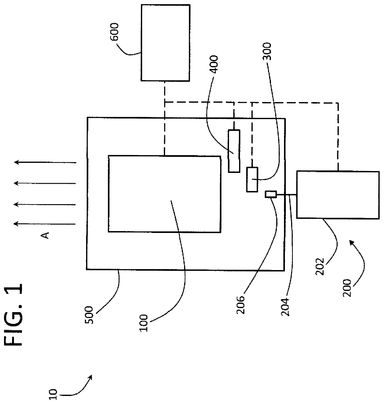
[0009]An aspect of the invention regards a device that emits colored flames. The device may include a fuel source, an ignition assembly, a flame coloring assembly an accelerator and a controller to control the functions of the foregoing. The device may also include a chamber or other packaging to position the foregoing components with respect to one another. In this aspect of the invention, fuel is ignited, a coloring agent is added and the ignited fuel / coloring agent mixture is directed to an accelerator which may emit the colored flames from the device. The colored flames emitted from the device of the present invention are preferably physically longer than flames provided by existing emitting devices, and may also last for a longer time.
[0010]Another aspect of the invention regards the addition of an inter gas, such as argon, to slow down the combustion reaction upon ignition so that the emitted colored flame may have a longer duration.
[0013]Another aspect of the invention regards including the colored flame emitting device into a display, to enhance the visual and other effects of such display.

Problems solved by technology

However, the physical size of the colored flames emitted by existing devices is generally limited (e.g., to a few feet).
In addition, existing devices do not provide a broad spectrum of primary colors and in-between hues.

Method used


Image

  • Colored flame emitting device
  • Colored flame emitting device
  • Colored flame emitting device

Examples


Embodiment Construction

[0020]A device according to exemplary embodiments of the current invention is described with reference to the figures.

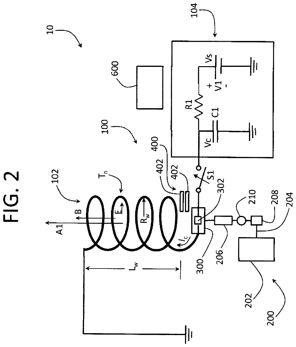
[0021]In general, and in some exemplary embodiments hereof, the device 10 may emit colored flames. The flames may be created by igniting a fuel to cause combustion and / or an explosion. The colors may be created by including additives within close proximity to the burning and / or exploding fuel that may emit visible colors upon thermal excitation. The reaction may occur in a chamber that may generally control the reaction and that may direct the colored flames in a desired direction(s). The colored flames may also be accelerated in a desired direction(s) by an accelerating device (e.g., a particle or ion accelerating device). The device 10 and its various components may be controlled manually and / or by a controller.

[0022]In general, the device 10 may include the following:

[0023]1. Fuel for a controlled explosion;

[0024]2. A chamber to contain the fuel and to generally c...


PUM

PropertyMeasurementUnit
lengthsaaaaaaaaaa
lengthsaaaaaaaaaa
lengthsaaaaaaaaaa

Abstract

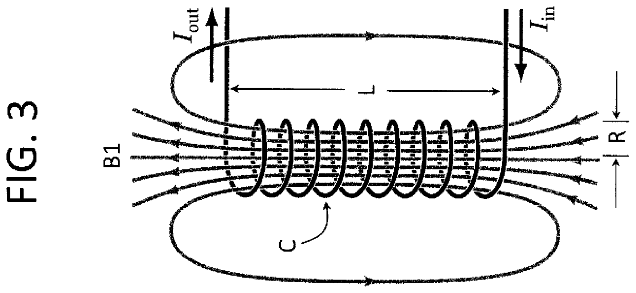
A device that emits colored flames is disclosed. The device may include one or more electromagnetic coils within a housing. A fuel source may provide fuel such as hydrogen to an igniter at the input to the electromagnetic coil. The fuel may be ignited and a current may flow through the coil that may create a magnetic field. The ignited fuel may ionize creating an electric current that may accelerate the combusting particles through the coil. The current may create a magnetic field that may force the ionized particles into cyclotron orbits. Coloring additive such as salts may be added to the combusting fuel to provide color to the resulting flames.

Description

COPYRIGHT STATEMENT[0001]This patent document contains material subject to copyright protection. The copyright owner has no objection to the reproduction of this patent document or any related materials in the files of the United States Patent and Trademark Office, but otherwise reserves all copyrights whatsoever.FIELD OF THE INVENTION[0002]This invention relates to flame emitting devices, including colored flame emitting devices, and their use in displays, such as displays with visual, audio and other effects.BACKGROUND OF THE INVENTION[0003]Colored flame displays and devices have been used for pyrotechnic effects such as for stage productions, fireworks, safety lighting / flares and for other purposes.[0004]However, the physical size of the colored flames emitted by existing devices is generally limited (e.g., to a few feet). In addition, existing devices do not provide a broad spectrum of primary colors and in-between hues.[0005]Accordingly, there is a need for a colored flame emit...

Claims


Application Information

Patent Timeline
Patent Type & Authority Patents(United States)
IPC IPC(8): C11C5/00F23C99/00
CPCF23C99/001C11C5/004
Inventor FULLER, MARKYOUNG, GARRETT
Owner WET ENTERPRISES
Learn More