
Apparatus and method to provide breathing support

a technology applied in the field of apparatus and breathing support, can solve the problems of inability to set and vary, device operation and maintenance, and high cost of devices, so as to improve patient gas exchange, stabilize lung volume, and reduce the likelihood of lungs damage

Active Publication Date: 2021-09-21
EUPNEA TECH
View PDF44 Cites 4 Cited by
  • Summary
  • Abstract
  • Description
  • Claims
  • Application Information

AI Technical Summary

Benefits of technology

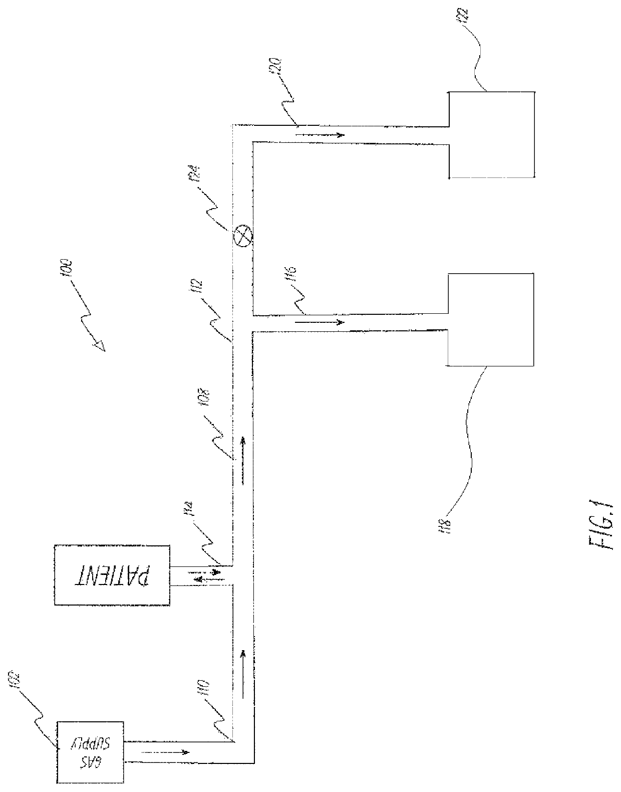
This patent is about a device and method that helps ventilate patients by controlling the pressure generated in the machine. It allows users to adjust settings like peak pressure, breaths per minute, and the ratio of inspiratory to expiratory time. This device is useful for adults, children, and newborn babies, and can be used in transport or without access to a mechanical ventilator. Overall, this invention helps improve lung function and gas exchange in patients who need ventilation assistance.

Problems solved by technology

These devices are generally expensive and out of reach of a large portion of the population, particularly in economically disadvantaged countries.
These devices also require substantial training and expertise to operate and maintain.
Further, these devices do not provide the user the ability to set and vary upper limit of safe positive pressure that is patient specific and commensurate with the peak inspiratory pressure levels set during ventilation in an easy and less expensive way.
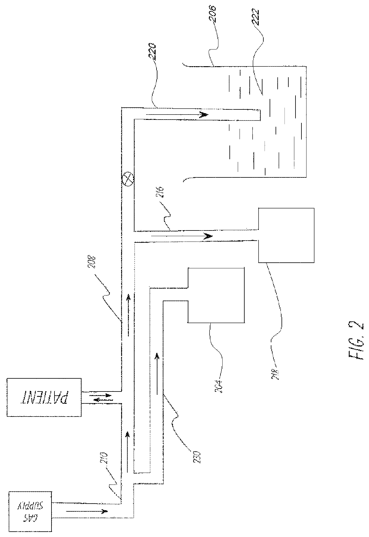
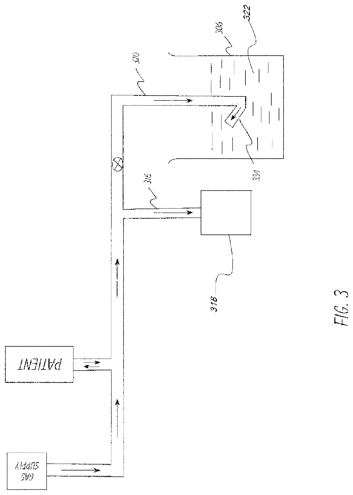
Further, such apparatus require a container containing a fluid.
The use of a container containing fluid may not be practical in certain conditions, e.g., when the patient is in a location where fluid is not readily available or fluid shakes and spills because of motion during transport of patients.

Method used


Image

  • Apparatus and method to provide breathing support
  • Apparatus and method to provide breathing support
  • Apparatus and method to provide breathing support

Examples


example 1

[0059]This example describes the ventilator system used and experiments performed to test the system described in FIG. 5. A lung machine manufactured by Ingmar Medical, Pittsburgh, Pa. (www.ingmarmed.com) was connected at patient interface of the ventilator system. Two different three-port valves were tested. (a) A three-port (three-way) solenoid valve manufactured by MAC Valves, Inc., Wixom, Mich. (www.macvalves.com) was used in the system. (b) A three-port (three-way) solenoid valve custom made with an orifice diameter of 10 mm. The cycling of the valve was controlled using an electronic timer made by IDEC Corporation, Sunnyvale, Calif. (us.idec.com). Compressed air and air / oxygen mixtures were used in the tests. The tubing used was the standard 10 mm plastic tubing used with conventional ventilator systems in a hospital setting. The pressure at the patient interface was measured using a manometer manufactured by Life Design Systems, Inc., Madison, Wis. The manometer had a range o...

example 2

[0062]This example describes the ventilator system used and tests performed using a system as shown in FIG. 12 wherein two two-port valves were used to determine whether two two-port valves would replicate the system and tests done in Example 1 where a single three-port valve was used. Two two-port solenoid valves manufactured by MAC Valves, Inc., Wixom, Mich. were used in the system. The size of the two-port (two-way) valve was the same as the three-port valve manufactured by MAC Valves, Inc. that was used in part (a) of Example 1. The first two-port solenoid valve was placed on the PIP control duct and is located between the PIP pressure-relief valve and the distal end of the primary duct. The second two-port solenoid valve was placed on the PEEP control duct and is located between the PEEP pressure-relief valve and the distal end of the primary duct. The test parameters were the same as those in Example 1. The two valves were controlled such that when the first valve was open, th...


PUM


Abstract

A ventilator, or a breathing assistance apparatus, is provided to ventilate patients who may have breathing difficulties, the apparatus comprising a inspiratory pressure control duct; a positive end-expiratory pressure control duct; at least one valve connected to the peak inspiratory pressure control duct and to the positive end-expiratory pressure control duct, and at least one controller communicably connected to the valve to control rate of cycling of the valve, thereby controlling number of breaths per minute, and to control the duration of peak inspiratory pressure also known as inspiratory time.

Description

CROSS-REFERENCE TO RELATED APPLICATIONS[0001]This application is a continuation of co-pending U.S. patent application Ser. No. 15 / 139,020 filed Apr. 26, 2016, which is a continuation-in-part of U.S. patent application Ser. No. 14 / 468,320, filed Aug. 25, 2014, now U.S. Pat. No. 9,345,850 issued on May 24, 2016, which claims the benefit of the earlier filing dates of U.S. Provisional Patent Application No. 61 / 874,323, filed Sep. 5, 2013; U.S. Provisional Patent Application No. 61 / 929,947, filed Jan. 21, 2014; and the above listed patent applications are incorporated herein by reference.FIELD[0002]Embodiments described herein concern devices and methods that assist gas exchange and stabilize lung volume in patients of all ages with breathing problems.BACKGROUND[0003]Patients who have breathing difficulties are conventionally provided breathing assistance using mechanical ventilators. These devices are generally expensive and out of reach of a large portion of the population, particular...

Claims


Application Information

Patent Timeline
Patent Type & Authority Patents(United States)
IPC IPC(8): A61M16/20A61M16/00A61M16/10
CPCA61M16/204A61M16/0051A61M16/024A61M16/201A61M16/202A61M16/205A61M16/209A61M16/1045A61M2016/0027A61M2205/3334A61M2205/3348A61M2230/205
Inventor SARDESAI, NOLAN RAJENDRARAMANATHAN, RANGASAMYSARDESAI, RAJENDRA GURUDAS
Owner EUPNEA TECH
Learn More